Six rules for alpha beta measurements in drill core
It is always better to know the orientation of planar structures at the time of logging rather than at some later date when the structure that was measured is long forgotten and the core returned to its stack in the yard.
The six rules are mostly common sense. With a little thought, and the help of an actual piece of core to play with, you could work them out for yourself. But employing them will greatly speed up the process of understanding the attitude of planar structure in oriented drill core at the time of logging.
Measurement of planar structures – such as bedding, veins or cleavage – in oriented diamond drill core can be done in two ways. The simplest way is to set up the core in its original orientation by means of a core frame and then measure structures within it using a geologists’ compass. The second way is to measure the angles which the plane makes with lines of known orientation in the core and then, knowing the hole orientation, use these angles to calculate the strike, dip and dip direction. This is called the internal core angles method. I described these methods in some detail in an earlier blog post and discussed the advantages and disadvantages of the two methods (Measuring structures in oriented core, Oct 19 2013).
But there is a third way: just eyeball the data and work it out for yourself. My six rules show you how to do this.
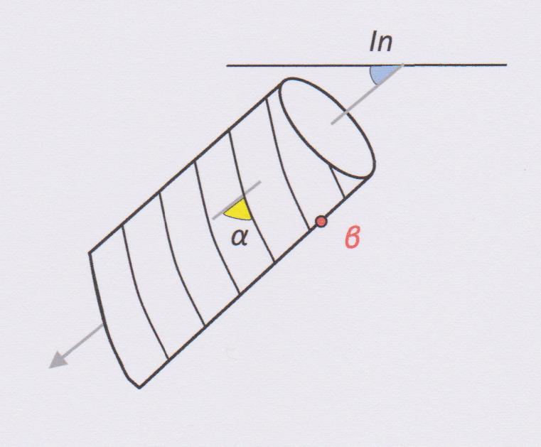
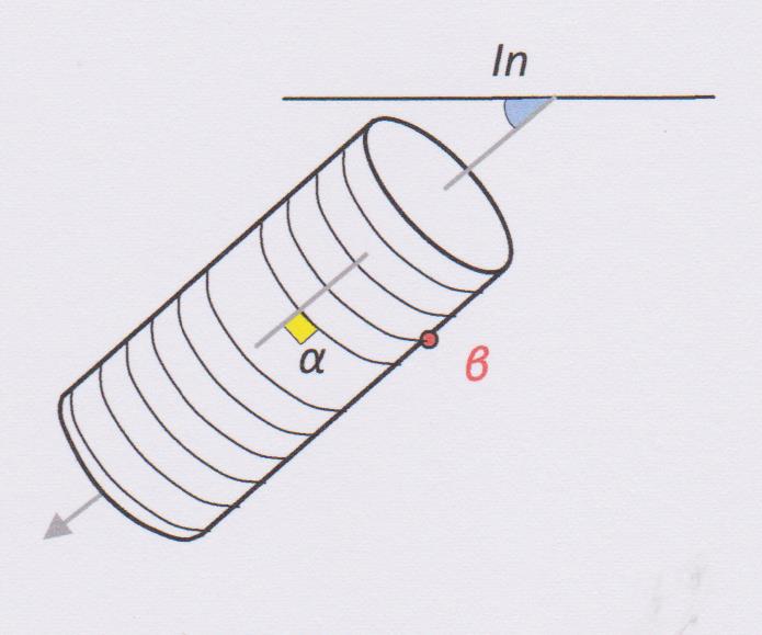
Before I present the rules, I will quickly recap the internal core angles method. The orientation of a planar surface intersected by drill core can be defined by two angles called alpha (α) and beta (β). The definition of these angles is shown in the diagram below:
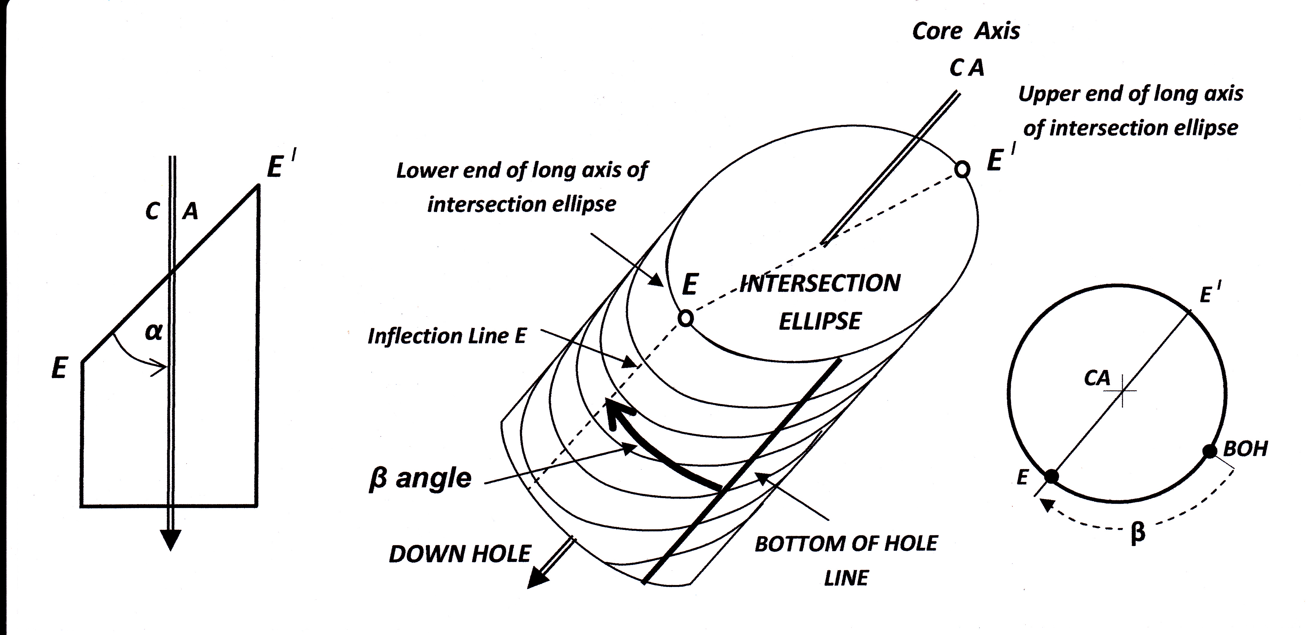
To be geologically useful, these alpha and beta numbers for a plane have to be converted into the more meaningful dip and dip directions. This conversion is usually accomplished by mathematical calculation (computer software) or less frequently by graphical means (i.e. a stereonet). How to use a stereonet to reduce alpha/beta angles is detailed in my blog post here.
In the discussion of Rules 1-6 that follow, note that no alpha or beta measurements made in core can ever be considered accurate to more than +/- 2 degrees. Therefore for 180° you should read 178° – 182°, for 0° read 358°-002° and for 90° read 88°-90°. If the alpha and beta angles are more than +/- 2 degrees away from the key numbers of 0, 90, or 180, the more we are into the area covered by Rule 1 – estimating approximate values for dip and dip direction. The further measured alpha and beta are from 0, 90 & 180, the more approximate that estimation will be.
Rule 1
When logging oriented core it is a simple matter to hold a piece of core in your hand and roughly orient it to its original in-ground attitude – your hand acting as a crude core frame. Most experienced geologists logging structure in core would do this automatically. By doing this one can eye-ball any planar structure in the core and quickly estimate its dip and dip direction. However, very often structures are analyzed ex post-factum on the basis of recorded observations long after the original structure is forgotten. All there is to work on is the record in the structure log. This is not an ideal situation, but all is not lost. We can recover the same quick qualitative assessment of dip and dip direction by visualizing the core in its original orientation and peopling it with a plane which would give the recorded measurements.
But why would you want an approximate dip and dip direction when you can use a computer program to calculate an exact one? A good question, but there are at least four good answers:
1. The process is quick.
2. An approximate answer may be all that you need to answer your structural question.
3. If mass data has been entered into a spread sheet for computer processing, knowing the approximate solution for any given measurement provides a quick way of checking the accuracy of the computer output (or more particularly of the data entry process, where errors are most likely to have occurred). This step is the essential one of quality control and validation.
4. For particular values of alpha and beta (as explained in Rules 2, 3,4 & 5) simple mental calculation involving adding or subtracting two-digit numbers can provide an accurate dip and dip direction.
Except in the few specific cases referred to in Answer 4 above, it is impossible for any normal person to mentally calculate an exact dip and dip direction from alpha and beta angles. However, by visualizing the angles on a mental image of the core, it is usually possible to produce an approximate estimate of the dip and dip direction of the plane – one good enough to be in the right ball park (1). I illustrate this with a random example (one sent to me by a reader):
a hole drilled at -44⁰ (dip below horizontal known as hole inclination In) to 031⁰ (the direction of drilling known as Azimuth Az) ; a plane in the core with internal angles alpha 09⁰ and beta 227⁰.
With just introspection it is possible to say that the plane must dip broadly to the east (the beta number tells you that) with a dip that is a bit steeper than the hole inclination (the alpha number tells you that).
The exact answer (which I calculated using a stereonet): is 54⁰ to 094⁰
If my calculation of had come up with a plane dipping at, say, a low angle to the NE, I would have instantly known that this was BS and I had made a gross error in my stereonet manipulation.
RULE 2
If β = 180º, then you are drilling at right angles to strike of the plane and in the direction of its dip. In this case…
Dip direction = Az
Dip = In – α
Rule 3
If β = 180° and angle α = In, then..
Dip = 0° (i.e. horizontal)
No strike can be defined (see footnote 1)
Rule 4
If β = 0º, then the hole is drilled at right angles to the strike of the beds. There are 3 possibilities for the dip:
(a)Where In + α < (is less than) 90º
Dip Direction = Az
Dip = In + α
(b) Where In + α > (is greater than) 90º, then….
Dip Direction = Az + 180º
Dip = 180 – α - In
(c) Where In + α = 90º, then…
Strike = Az + 90º (Note: no dip direction can be assigned)
Dip =90º (i.e. Vertical)

Rule 5
If α = 90º, then the hole is drilled at right angles to the strike of the plane in a direction that is opposed to the dip of the beds. There is no useful definable beta angle (if you think you can measure a beta angle then the number you get is meaningless – see Rule 6). The relationships are these:
Dip direction = Az + 180º
Dip = 90º – In
Rule 6
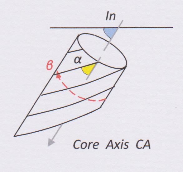
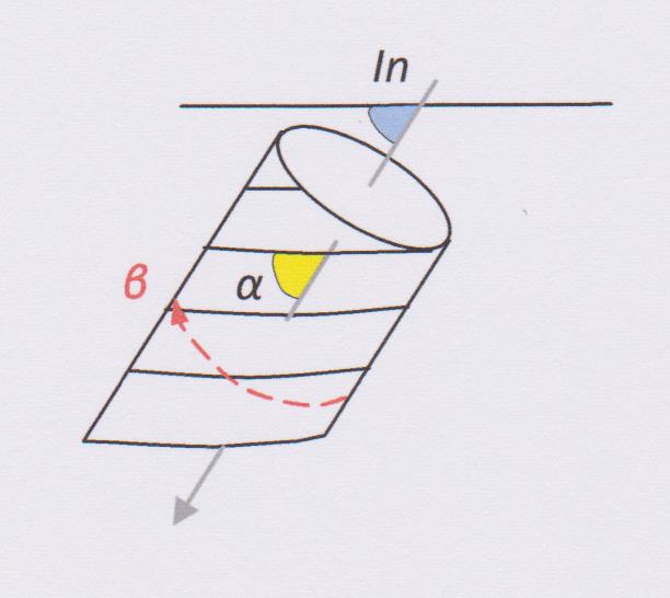
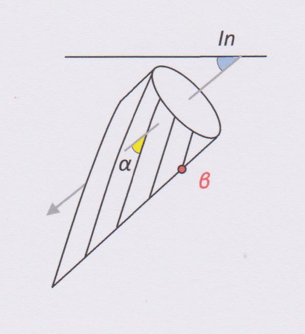
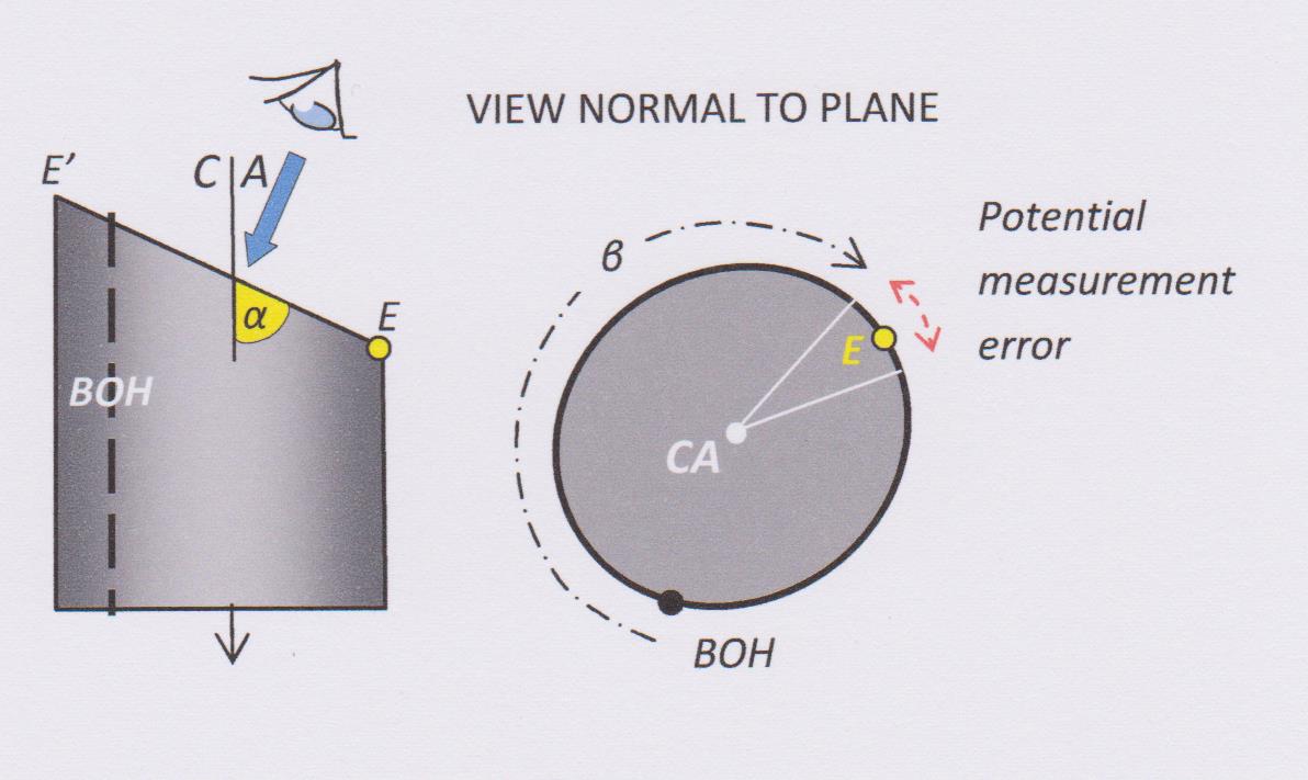
As the angle alpha approaches 90°, the intersection ellipse on the core surface approaches an intersection circle on which no unique long axis can be defined (see Rule 5). For large α angles it is therefore not possible to define the point E (or E’) on the core surface with sufficient accuracy to enable an accurate measurement of the beta angle to be made. Small errors in measuring beta can produce large errors in the calculated strike and dip for that bed. How large does alpha have to be make errors in the corresponding beta angle unacceptable? There is no fixed cut-off point: every increase in alpha above 50° causes potential measurement error in beta to rise exponentially. Experience suggests any alpha angle greater than 65º is large - but how much error you are prepared to tolerate is a matter for judgement and is to some extent dependent upon how well the plane is defined in core and how many parallel planes of that orientation are present.
Where large alpha angles are encountered the alpha/beta method should not be used and core should be set up in a core frame and the surface measured with a geologists’ compass.
***** ****
(1) Computer software will calculate an exact strike (or dip direction) for a plane, even if the difference between the alpha angle and the hole inclination is a fraction of a degree. However, if the difference between these two angles is 10 degrees or less, the calculated dip direction is essentially meaningless, since even the smallest error in measuring either α or In will lead to an order of magnitude greater error in the calculated strike. This is the same problem as trying to measure the strike of near-horizontal beds exposed at surface: but the problem is much more acute in drill core because of the small area of exposed surface.
******
Please note that this blog no longer accepts comments (there was too much spam coming in!) However, I welcome your opinions, comments even criticisms. You can contact me direct through the email form on the Contacts Tab.