There are two ways of measuring structures in oriented diamond drill core. The first is to set up the core in a core frame (often called a “rocket launcher”) so that it lies in the same orientation as it did when it was in the ground; the structures within the core are then measured using a geologists’ compass – just as a structure exposed in a surface outcrop would be measured. The second is to use a protractor to measure the angles which the structure makes with lines and planes of known orientation (the core axis, the Bottom-of-Hole orientation line) and to use these angles to calculate the strike and dip (if planar) or the trend and plunge (if linear) of the structure. This is known as the internal core angles method.
The Rocket or the Protractor – which is the best technique?
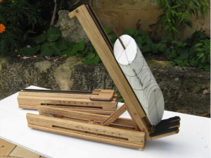
For most applications, it is recommended that a core frame be used to measure the orientation of structures. Core frames are a cheap, low-tech and readily available tool. One is illustrated below. The frame permits direct visualization of structures in their original orientation, and allows them to be measured in terms which have geological meaning at the time they are made. Setting up core in a frame permits not only measurement of individual structures but, importantly, allows the relationships between sets of structures in the same piece of core to be observed. Measurements can be constantly compared against the evolving geological model for the deposit as the core is being logged. Significant changes in attitude of structures can be identified and examined in more detail while the core is still laid out. Mistakes in measurement (or problems with the core orientation line) can be quickly spotted. In short, Core Orientation Frames are GEOLOGIST FRIENDLY. Even where the method of measuring internal core angles is being used, a core frame must also be available in order to measure planes with high alpha angles[1]. In addition, a core frame is the only way in which non-penetrative linear structures – such as fold axes – can be measured.
A Core Orientation Frame – sometimes called a “Rocket Launcher” It enables a piece of oriented core to be set up in the same orientation as it was when part of mother earth. Structures can now be measured with a geologist’s compass in the usual way. For most applications in logging core, the use of a core frame is recommended.
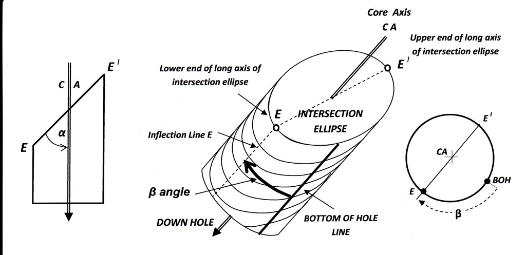
The internal core angle technique involves measuring two angles referred to as alpha and beta. These two numbers (meaningless in themselves) are then fed into a computer where they are crunched with down-hole survey data to produce the attitude of the measured structure in terms of a standard dip and dip direction measurement. This number processing can also be done manually using a stereonet — It’s not hard and takes only a few seconds once you have mastered the technique. You can find full details of the stereonet technique elsewhere in my blog (LINK) and also in my book “Geological methods in mineral exploration and mining” (Springer 2011).
Definition of the angles that a planar structure makes with the Core Axis (CA) and the Bottom of Hole (BOH) lines in surveyed and oriented diamond drill core. The alpha angle is the acute angle between CA and the line E-E (the long axis of the intersection ellipse). The beta angle is the angle between the Bottom of Hole (BOH) line and E. This measured around the core circumference in a clockwise direction when looking down the hole. The beta angle can range from 0 to 359 degrees.
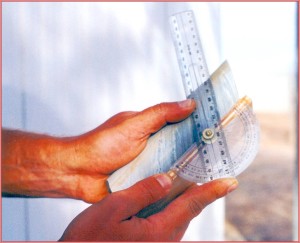
Using a simple home-made protractor to measure the alpha angle of a planar structure in a piece of oriented drill core.
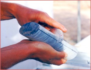
Measuring the beta angle of a planar structure in a piece of oriented drill core. The black line marks the bottom of hole (BOH) : it represents the intersection of the original vertical plane with the core and has been determined by a special down-hole core orientation survey procedure. The protractor is a basic school plastic 180 degree model ($2.80 – any good stationer or newsagent) cut to fit the core circumference. More elaborate beta-angle protractors are sold commercially, but none are as accurate or as easy to use as this design.
The alpha-beta method was developed in 1979 by the geotechnical engineer R E Goodman as a means rapidly taking a large number of measurements that could be plotted in bulk and analysed statistically. Statistical handling of bulk plots has value in geotechnical studies but tends to obscure geological relationships by promoting quantity over quality. Nevertheless, the speed and ease of making alpha/beta measurements as digital computer feed, and the fact that it is a mechanical, mindless process which obviates the geologist from actually having to think about the meaning of what he or she is actually looking at, has made the technique very popular. It is fair to say that in most drilling programs using oriented core, the alpha-beta method is now the technique of choice from the very first exploration hole through to final ore definition drilling. The reality is that the transfer of this technique from the geotechnical engineering field to the structural geology field has been, with few exceptions, a disaster for geological understanding. It encourages a culture of filling data bases with thousands of meaningless numbers in the hope (seldom fulfilled) that somewhere there is a computer program that will tell the geologist what it all means.
Geologists should always resist being turned from professionals whose brains are actively engaged with the material they are examining into mere operatives – collectors of endless numbers to be entered into computer data bases.
Data is not information
Information is not knowledge
Knowledge is not understanding
Understanding is not wisdom
POSTSCRIPT:
Well he would say that wouldn’t he? (He sells core frames, after all.)
Lest I be thought biased, I must point out that the internal core angles method of measuring planar structure in core does offer some advantages over using a core frame:
- Measuring alpha/beta angles is much faster than using a core frame.
- If the requirement is to make a very large number of measurements of a set of planar structures, whose identification and significance are otherwise well understood, with a view to a statistical treatment of the results, then the internal core angle technique, with computer processing of the results provides the quickest and most effective option. This situation can arise, for example, in a mine application, in geotechnical logging or in the advanced infill drilling stages of prospect exploration. In this case, the internal angles would normally be entered directly onto a spread sheet type of log form (or directly into a portable computer) for subsequent processing. Presentation will usually be in the form of a computer generated section or map, a stereonet pole figure or a histogram. However, even for these applications, the inherent limitations (often impossibility) on the use of this method, for planes with particular orientations, or for measuring non-planar structure, need to be borne in mind.
- Measuring internal core angles may be the most efficient method of recording structure attitude onto analytical spread-sheet type logs during the advanced drilling stages of a prospect.
[1] As alpha angles increase, the ability to measure an accurate beta angle decreases. The relationship is not linear but exponential. Specifying a cut-off point for use of the method depends on particular circumstances (how planar the structure, how well defined, how penetrative etc..) but, in general, for all alphas over 65°, the inability to measure an accurate beta becomes too great to allow meaningful calculation of dip and dip direction. Few geologists using the internal angles method are aware of this, and inaccurate beta measurement are routinely entered into data bases, creating a significant GIGO effect for any subsequent computer processed output.


