All metal deposits that have formed later than the rocks that host them (that is, epigenetic deposits) have got there by virtue of fluid transport along faults and their location, shape, size and attitude are largely determined by the strain states that existed within the fault and its immediately adjacent rocks during fault formation. The most important structures for any explorationist to understand are therefore faults.
What is a fault? The answer seems so obvious that few geologists (or textbooks) ever bother with a definition. When geologists think of a fault, they have in mind a fracture where the rocks on either side have slid past each other with the direction of movement lying in the plane of the fault itself. Most geological dictionary, or structural geology textbooks reflect this same misunderstanding with a definition that specifies a direction of movement along the plane of the fault. For example the Glossary of Geology (American Geological Institute, 1980) defines a fault as:
A fracture or zone of fractures along which there has been displacement of the sides relative to one another parallel to the fracture.
Hobbs, Means & Williams in their textbook An Outline of Structural Geology (1976) provide this definition:
A .(fault is a)..planar discontinuity between blocks of rock that have been displaced past one another in a direction parallel to the discontinuity
However, these definitions are wrong because, if strictly applied, they would exclude almost all structures that geologists normally understand by the term fault.
Here is my definition: a fault is a fracture, or zone of fractures, across which relative displacement of the rocks on either side has occurred.
Let us add some meat to this definition and describe the range and scale of the structures that we are dealing with.
- The direction of relative movement of each side of the fault with respect to the other is called the Fault Movement Direction, or Fault Movement Vector. It can be represented by a pair of opposed arrows across the fault trace, as shown on the diagram below.
- The amount of movement across a fault can vary from a fraction of a millimetre to hundreds of kilometres. Small, locally developed, fracture surfaces across which insignificant displacement (difficult to see with the naked eye) has taken place are called joints. Joints form in exactly the same way as faults, and should be regarded as a special sub-category of faulting.
- Faults are not mathematical planes (two-dimensional surfaces with length and depth, but no width) but a three-dimensional tabular zone of deformed rock. The length and depth of a fault is many orders of magnitude greater than its thickness, but fault thickness (especially in large ductile faults) can range up to many kilometres. No fault is strictly planar.
- No fault is strictly planar,even in the non-mathematical sense. Normal and reverse faults (see diagram below) typically are curved: steep dipping near the surface and progressively flattening with depth – a shape known as listric. In addition, at all scales, faults show irregularities – bends and bumps and jogs. During fault movement the variations from strict planarity lead to complex patterns of stress along the fault surfaces. These stress variations are the key to understanding the location and shape of ore shoots within the fault zones.
In the definition of the fault given here, the Fault Movement Vector can lie at any angle to the fault surface. Where the vector lies within the fault plane the fault is a Simple Shear Fault. Where the fault movement direction is at 90° to the fault surface the fault is a Pure Shear structure. In pure shear faults the rocks on either side of the fault have either moved towards each other in compression, or moved apart in extension. Most fault zones are the result of both simple shear and pure shear deformation processes, although the amount of displacement attributable to simple shear is usually the greatest.
Pure shear compression in rocks can only take place by the removal of material from the faces of the fault zone. This happens predominantly through the process of pressure solution and is aided by high temperatures and confining pressures. Material dissolved in fault fluids moves along (laterally and upwards) the fault zone driven by pressure and temperature gradients as well as by periodic episodes of ”seismic pumping”. It will ultimately be deposited as vein material (typically quartz) elsewhere in the fault in regions that are under relative tension. Left behind in the fault zone are relatively insoluble rock components such as clay or graphite. Any puggy, clay-rich material (fault gouge) in a fault is the insoluble residuum of material lost through pure shear compression.
Pure shear extension creates dilation zones that are normally filled with dyke or vein material. Such are the so-called ”dilational jogs” that host many epithermal ore deposits.
The important point to remember is that pure shear deformation, as opposed to simple shear deformation, always results in a change in volume (increase or decrease) of the affected rocks.
DIFFERENT TYPES OF FAULT MOVEMENT
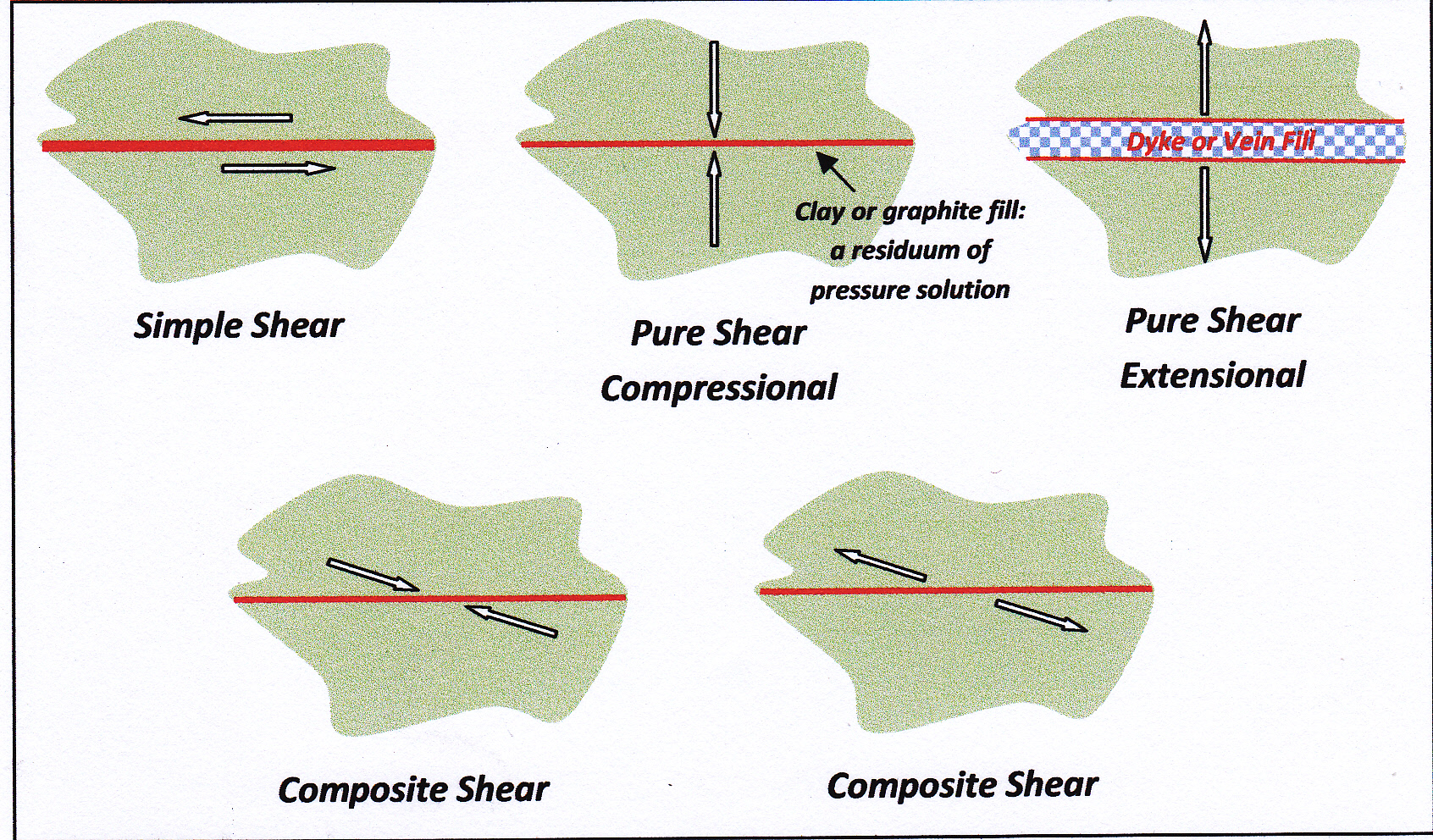
The above diagram shows a series of two-dimensional slices through rock bodies affected by different types of faulting. Think of them as maps or sections. The arrows show the relative movement of the rocks on either side of the red fault trace. The movement is either past each other, towards each other, away from each other or some intermediate type of movement between these end member states. They are the Fault Displacement Vectors for that map or section. The arrows should not be confused with the little opposed arrows that geologists often place on their mapped fault traces to indicate the apparent displacement of marker horizons across the fault .
Simple Shear and Pure Shear faults are end members of a continuum of styles of rock fracture. Even where Simple Shear might be the predominant fault mechanism, different parts of the fault will locally exhibit the effects of pure shear (either compressional or extensional). In dominantly pure shear structures, there will be zones where the structures observed formed through the process of simple shear.
Faults develop incrementally over geological time through the accumulation of large numbers of relatively-small movements. During this process each part of a final fault structure may have been sequentially subjected to, and show the effects of, both simple shear and pure shear mechanisms. Therefore, in addition to evidence for different structural process that can be found in different parts of the one fault, at any one point in a fault different styles of faulting may have operated over time. 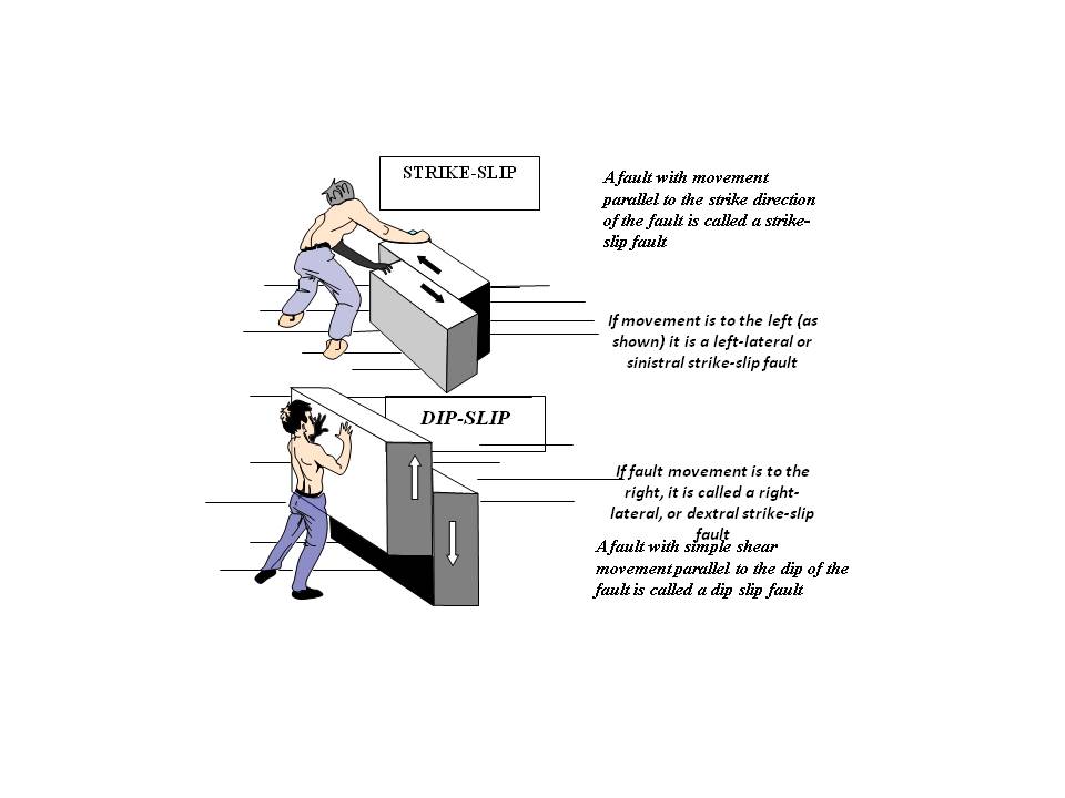
Above: Basic descriptive nomenclature for Simple Shear Faults where the Movement Vector lies within the fault surface
Below: Dip-slip faults that have a dip of less than 90 degrees come in two flavours: Reverse and Normal. Low-dip Reverse faults are called thrusts. With thrusts and reverse faults, movement shortens the affected rocks in the horizontal direction and increases them in the vertical dimension. With normal faults, the affected rocks are extended horizontally and compressed vertically. In contrast to pure shear compression and extension, there is no overall change in rock volume. The sections below illustrate these categories.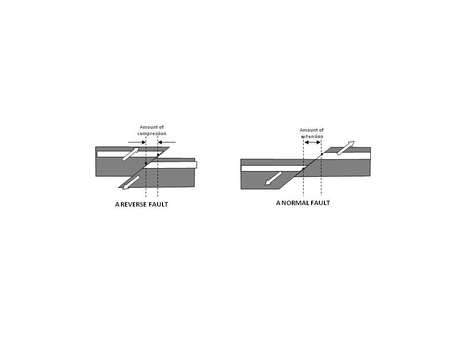
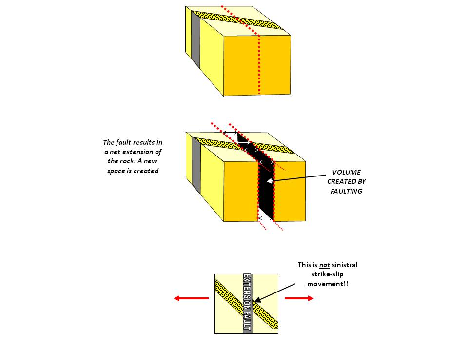
Above: A Pure Shear Extensional Fault in block and plan view. The fault is usually filled with dyke or vein material.

- Above: A Compressional Pure Shear Fault in block and plan view.