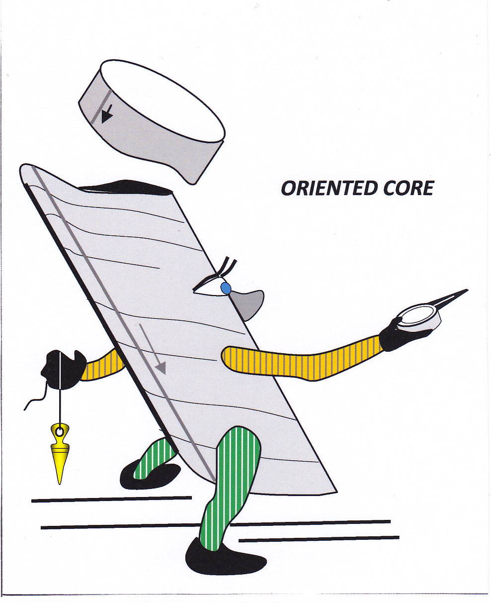
Measuring Structure in Non-Oriented Drill Core
My drill core is not oriented. How do I measure structure?
Down-hole orientation surveys record the deviation of a drill hole from its initial azimuth and inclination. However, the solid stick of drill core (sometimes, not so solid) recovered from a hole is not fully oriented by a down-hole survey. Although such surveys give the azimuth and inclination of the core axis at any given down-hole depth, the core itself has another degree of freedom in that it has rotated by some unknown amount about its long axis. This does not affect a lithological log made of the core (the down-hole depth to any given point on the core axis can still be measured), nor the ability to measure true thickness of beds (see figure 6, below), but the original attitude of structures (i.e. their dip and dip direction relative to geographical coordinates) cannot be directly determined. Techniques are available to fully orient the drill core (see previous posts in this series) and in all cases, when drilling into unknown rocks, it is recommended that these are employed[1]. However, orienting core adds expense and time to any project; some managers are just not prepared to spend the money and some drilling companies are not equipped or have the knowledge to do this. In any case much historical core that geologists have to deal with is not oriented (and orientation can never be done post-facto).

But all is not lost: it is still possible to make useful quantitative structural measurements on non oriented core.
How to measure structures in a single non-oriented core is the subject of this post. Much of the material is taken and adapted from Marjoribanks, 2003 and 2011[2].
In many cases rocks contain a penetrative planar fabric such as bedding or cleavage whose orientation is known from surface mapping. In these cases, if this surface can be identified in the core, and the assumption can be made that its attitude is constant, the surface can be used to orient the core. A cleavage is a better surface to use for this than bedding because the attitude of a cleavage, being a later tectonic surface, is generally more constant than that of bedding (Annels and Hellewell, 1988[3]).
Place a piece of core containing the structure to be measured in a Core Orientation Frame set up at the appropriate azimuth and orientation for the drill hole. Rotate the core about its long axis until the known structure is in the correct orientation according to your compass and clinometer. Now the orientation any other structures present in the core (such as mineral veins, fold axes etc.) can be directly measured with your geologists’ compass.
A common situation occurs when a hole is drilled at right angles to the strike of a planar structure whose dip is either not known or else is suspected of changing through the length of the hole, perhaps as the result of folding. This is a situation that often arises when drilling surface geochemical or geophysical anomalies. The situation also commonly arises when surface mapping is able to establish the strike of extensive planar rock units, but accurate dips cannot be determined. In non-oriented core all that can be measured of the dominant planar structure is the angle alpha (α) – the angle that the surface makes with the long axis of the core. Since the strike is known (or confidently assumed), and the hole is drilled at right angles to strike, the surface can be plotted on the drill section in only two possible attitudes, that is, symmetrically disposed at angle alpha about the hole trace (see figure 1, below). In many cases simple inspection of the two geometric possibilities for the attitude of the measured surface will lead to one of them being discarded as unlikely.

Figure 1: How to plot the attitude of surfaces in non-oriented core where the strike of the bed is known, but the dip is not (i.e. assuming the hole azimuth is normal to strike). Of the two possibilities plotted, one can often be discarded as unlikely. Click for full size figure.
In the general case where neither strike nor dip of a surface is known, then the angle between that surface and the core axis (the angle α) defines half of the apical angle of the cone that would be produced if the surface were rotated 360° around the core axis. This is illustrated in figure 2, which shows the range of possible attitudes of a surface on rotating the core about its axis. In this case, no absolute measurement of the attitude of the surface is possible, but it is still worthwhile to plot the boundaries of the cone of lines on to the drill section to represent the limits to the range of possible solutions to the true orientation of the surface. Small ticks placed on the ends of these lines on the section indicate the limits to the domain within which the surface will intersect the section.
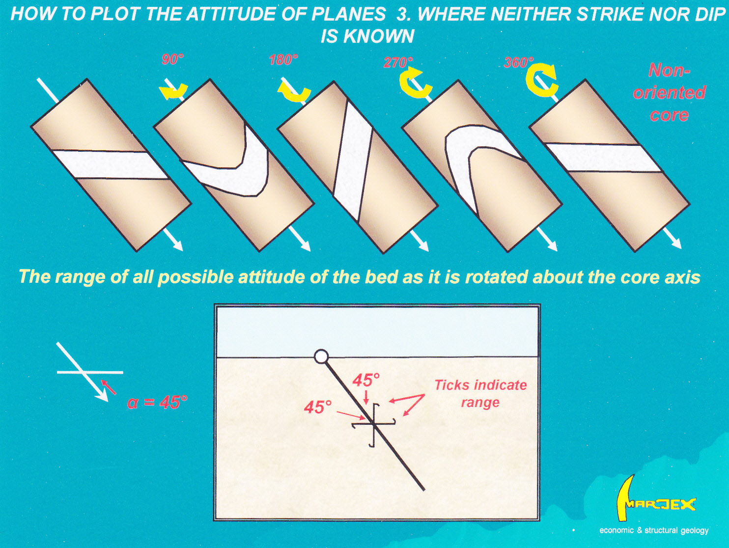
Figure 2: How to plot the attitude of a surface where neither its strike nor dip is known. On the trace of the drill hole on section two lines with ticks indicate the range of possible attitudes defined by the alpha angle. Click for full size figure.
Two special cases exist. One, where the surface is normal to the Core Axis (α = 90°), and two, where the surface trends parallel to the Core Axis (α = 0°). With real core and real world measurements, of course, these situations can be taken as any α alpha over 85° or under 5°.
- Where (α = 90°) you are drilling at right angles to the strike of the surface and the true dip is 90°- the hole inclination. Rotation around the Core Axis gives no apparent change in attitude. The surface can therefore be plotted unambiguously on to the drill section as a short line at right angles to the hole trace (figure 3). However, note that the core is still not fully oriented, and other planar or linear structures that might occur within it (that are not normal to the core axis) still cannot be fully measured.
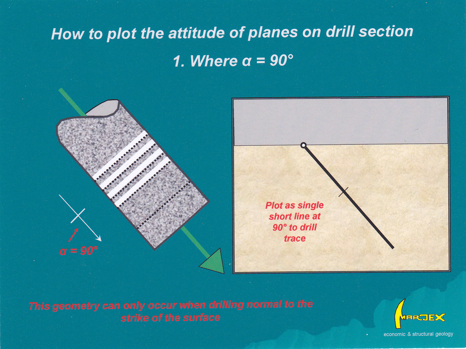
Figure 3 How to plot the attitude of surfaces in non-oriented core where the surface is at 90° to the core axis (α = 90°). This situation can only arise when drilling at right angles to strike. The dip shown on the section is therefore a true dip. However, the core is still not fully oriented, as the attitude of any surfaces not at 90° to the core or any linear structure still cannot be measured. Click for full size figure.
2. The second case (where α = 0°) means that your drill hole lies within the surface you want to measure. The trace of the bed on the drill section can be shown as a single short line parallel to the drill trace (figure 4): but note – this line represents an apparent dip only: it would only be a true dip if you were drilling at right-angles to strike[4]. But you still know something about the dip: remember, apparent dips can never be greater than true dips. So you know that the true dip of the surface cannot be less than that shown on your drill section.
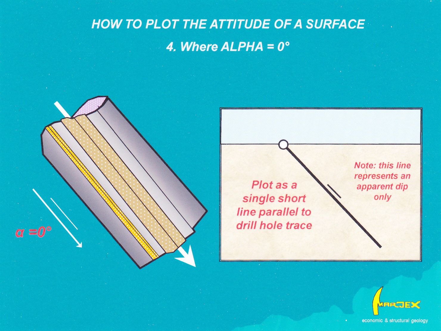
Figure 4 How to plot the attitude of surfaces in non-oriented core where the alpha angle is 0°. Note that this is an apparent dip only, unless the hole is drilled at right-angles to strike. Click for full size figure.
For the general case where no assumptions can be made about the attitude of structures in the core, absolute measurement can only be made if the core is mechanically oriented by means of a core orienting device. From oriented core you can measure the strike and dip of the surface. If it turns out that you are not drilling at right angles to the strike of the bed (the most likely situation) then the intersection of the measured surface on the drill section will be an apparent dip. This is illustrated in Figure 5. Knowing the true orientation of the surface, its apparent dip on section can be calculated using a stereonet or by looking up a table of apparent dips[5].
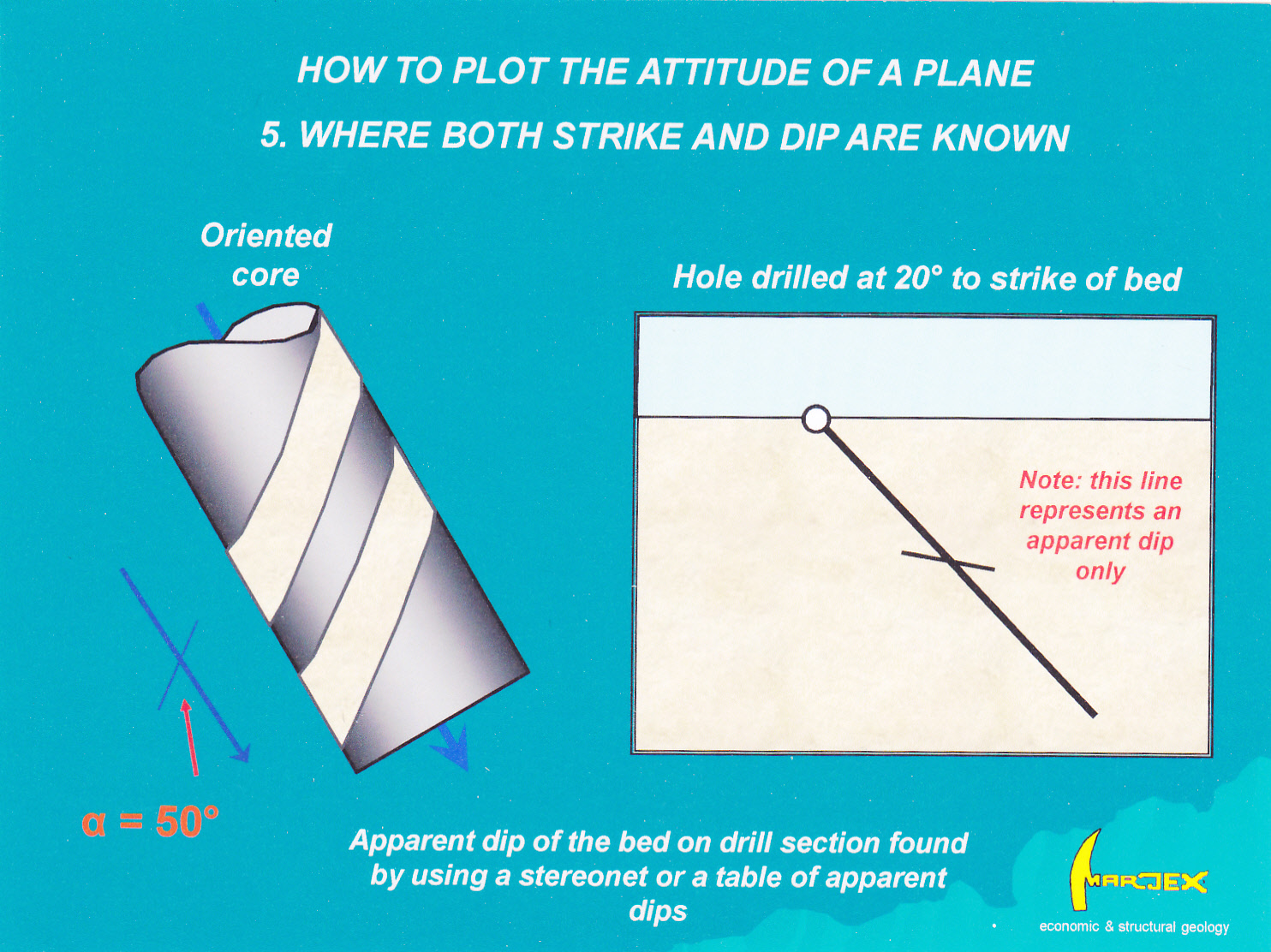
Figure 5 How to plot the attitude of a plane on a drill section when both the strike and dip are known. Click for full size figure.
Even where core is not oriented, it is still possible to make a large number of useful structural observations and measurements. For example:
- Qualitative observations on the style and nature of structures.
- The relative ages of structures and their relationships to lithology, veining and alteration.
The only orientation measurement on a surface that can be made in non oriented core from a single drill hole is the alpha angle. Taking and recording alpha angles for planar structures is quick and easy to do and should be a routine procedure in all core logging. From the alpha angle is possible to use simple trigonometry calculate the true thickness of any tabular bed or vein intersected by the core. How to do this is illustrated in figure 6, below.
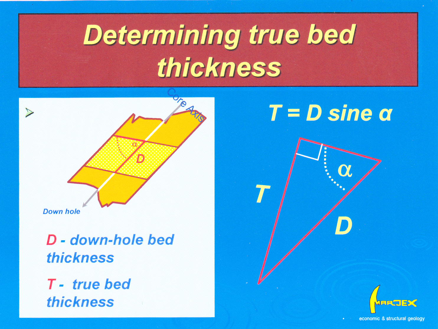
Figure 6 How to calculate the true thickness of beds in core. All that is needed is the alpha angle. It is not necessary for the core to be oriented, or even to know the azimuth and inclination of the drill hole. Click for full size figure.
In this post I have described methods for obtaining quantitative structural data from a single non-oriented drill core. If a number of drill holes have been drilled into a property then an additional range of techniques are available to acquire this data. These will be the subject of the next post under the heading “The three point problem”
Note this blog does not accept comments any more (there was too much Spam coming in!). However you can use the CONTACT ME tab and comments, criticisms questions etc. are welcome.
[1] How to do this, and how to mark up and measure structures in oriented core are covered in some of my other blog posts.
[2] Marjoribanks RW (2003): Structural logging of drill core.AIG Handbook 5, 73p
Marjoribanks RW (2011): Geological methods in mineral exploration and mining. Springer 238p
[3] Annels AE & Hellewell EG (1988): The orientation of bedding, veins and joints in core; a new method and case history. Int J Min Geol Eng 5(3): 307-320.
[4] An apparent dip is the dip of the intersection of any randomly-oriented vertical plane (in this case, the drill section) with a surface. The true dip is the special case where the intersecting vertical plane is at right angles to the strike of the surface.
[5] A table of apparent dips can be found in “Geological methods in mineral exploration and mining” page 203.