TARGETING DRILL HOLES
It is a truism that ore bodies are rare and hard to locate. If this were not so, they would hardly be worth finding. Explorers search for them by drilling holes into the ground. A single drill hole produces a very small sample of rock: ore bodies, even the largest of them, are of insignificant size relative to the barren rocks that surround them. Even after an initial discovery hole has been made into a potential ore body, if the subsequent holes are poorly positioned, the ore body may remain undiscovered, or, at best, an excessive number of holes will be needed before its true shape, attitude and grade are defined. Western Mining Corporation, after their first serendipitous intersection of the blind Olympic Dam Au-Cu-U deposit in South Australia, required another nine holes (and 1 million 1975 exploration dollars) before they could find it again. And this was one of the largest metallic ore bodies on the planet.
For the most efficient path to discovery, the explorationist has to make use of all available knowledge.
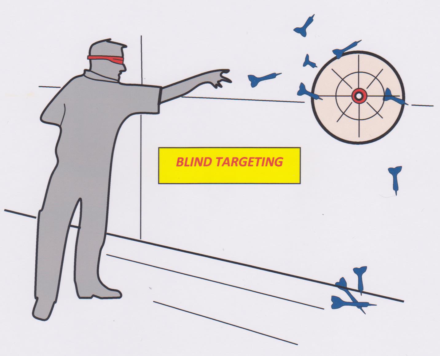
When geologists drill targeted holes they are testing a mental model of the size, shape and attitude of a hoped for ore body. The more accurate that model, the greater the chance that the hole will be successful. The model is the result of extensive detailed preparatory studies on the prospect, involving literature search, examination of known outcropping mineralisation, geological mapping at regional and detailed scales as well as geochemical and geophysical studies. Compared to drilling, such preliminary studies are relatively cheap. Each drill hole into a prospect, whether it makes an intersection of mineralisation or not, (and perhaps especially if it does not), will increase geological knowledge and lead to modification or confirmation of the model and so affect the positioning of subsequent holes. The first few targeted holes into a prospect are always hard work, this is the steepest part of the learning curve, and it is in how this stage of exploration is approached that exploration geologists most clearly reveal their true worth.
In order to most efficiently define the size and shape of a potential ore body, drill holes will normally be aimed at intersecting the boundaries of the mineralisation at an angle as close to 90° as possible. If the expected mineralization has a tabular, steep-dipping shape, the ideal drill holes to test it will be angle holes with an inclination opposed to the direction of dip of the body. If the direction and amount of dip is not known (as is often the case when drilling in an area of poor outcrop, or testing a surface geophysical or geochemical anomaly), then at least two holes with opposed dips, intersecting below the anomalous body, will need to be planned in order to increase the chances of intersection the target at depth. Flat-lying mineralization (such as a recent placerdeposit, a supergene enriched zone above primary mineralization, or perhaps a manto deposit) is normally best tested by vertical holes. These are not the only considerations. Holes are normally positioned to intersect mineralization at depths where good core or cuttings return can be expected. If the target is primary mineralization, the hole will be aimed to intersect below the anticipated level of the oxidized zone.
Once an intersection in a potential ore body has been achieved (a situation often described as having a “foot-in-ore”, although “toe-in-ore” would often be more accurate), step out holes from the first intersection are then drilled to determine the extent of the mineralization. The most efficient drill sampling of a tabular, steep-dipping ore body is to position deep holes and shallow holes in a staggered pattern on alternate drill sections. However, the positions selected for the first few post-discovery holes depend on confidence levels about the expected size and shape of the deposit and, of course, on the minimum target size sought. Since the potential horizontal extent of mineralization that has an expression at surface is usually better known than its depth extent, the first step out hole will in most cases be positioned along strike (at a regular grid spacing in multiples of 40 or 50 m) from the discovery hole, and aimed to intersect the mineralization at a similar depth. Once a significant strike extent to the mineralization has been proven, deeper holes on the drill sections can be planned.
Epigenetic[1] vein or lode type deposits occur as the result of mineral deposition from fault fluids in localised dilation zones that result from fault movement. These dilation zones may lie within the main fault or in splays from or adjacent to it. High grade ore shoots therefore will tend to have the same shape and orientation as the dilation zone[2]. Dilation zones in faults are typically highly elongate, with a flat, blade-like cross section. An elongate ore body of this sort is known as an ore shoot. If the long axis of the shoot has a shallow pitch[3] on the fault plane, any hole targeted to drill below a surface indication or initial discovery hole is likely to pass below the shoot and so miss it. If the ore shoot pitches steeply, a hole collared along strike from an initial discovery hole may lie well beyond the shoot. Obviously, being able to predict the pitch of an ore shoot is important. How can we do this? The answer lies in understanding the nature of the fault structure which controls it.
The shape and orientation of dilation zones reflect the stresses that produced the fault and local variations in the physical properties of the rocks being faulted. A detailed theoretical treatment of the stress/strain relationships of faults is beyond the scope of this blog but can be found many standard texts (for example Ramsey and Huber, 1983,) and published papers (for example Nelson, 2006). However, the exploration geologist is a generalist with little time or opportunity for reading academic papers. She needs practical rule-of-thumb guidelines. For that purpose, the following brief description of fault geometries will be found useful in predicting the attitude of high grade epigenetic ore shoots that might have formed within them.
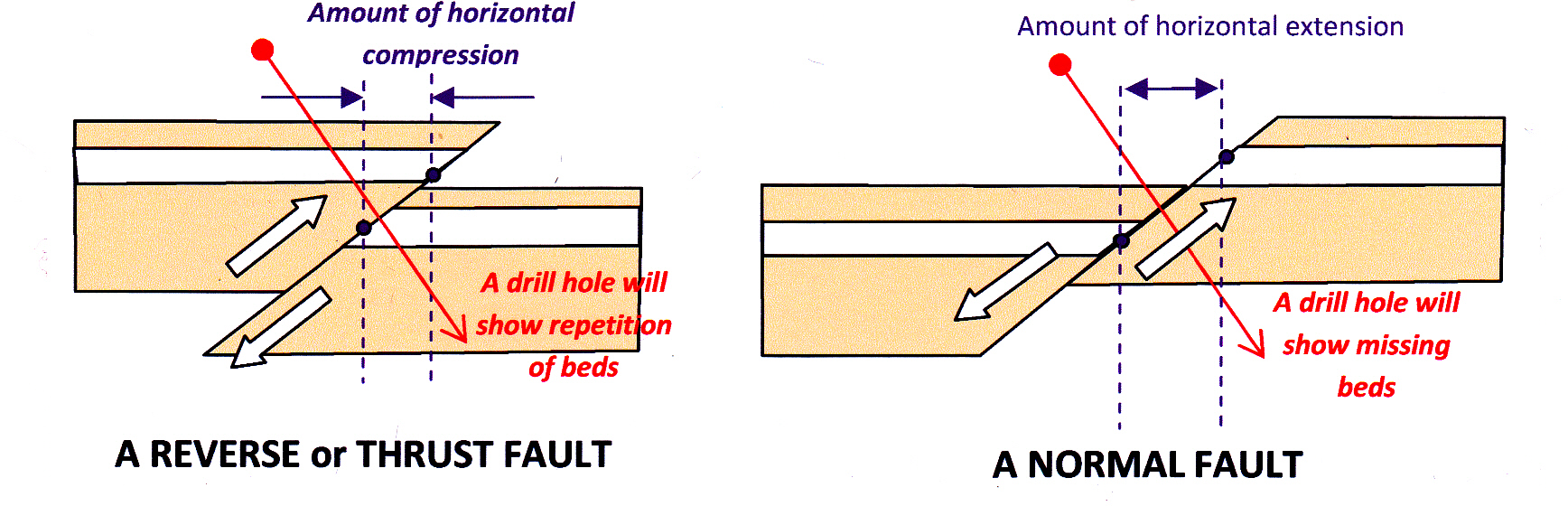
Most faults that form in the upper few kilometres of the earth’s crust result from principal stress directions that are, to a first approximation, oriented either parallel to, or normal to, the earth’s surface. This has produced three common classes of fault : normal faults, thrust (or reverse[4]) faults and strike-slip faults, depending on which one of the three orthogonal principal stress directions is vertical. Normal faults are the commonest type of fault to form in the upper 1-3 km kilometres of the crust: they are steep dipping, but tend to flatten with depth. In normal faults, the direction of movement across the fault lies in the direction of the dip of the fault such that fault movement produces a horizontal extension of the crust. Thrust and reverse faults are generally shallower-dipping than normal faults. Once again the direction of movement across the fault lies in the direction of the dip of the fault but in this case the movement direction is such that that it causes a horizontal compression or shortening of the crust.
 Strike-slip faults are always steep dipping with a movement or displacement direction in the direction of the strike of the fault. This movement is either left-lateral (where, on looking across the fault, the rocks have been displaced to the left) or right-lateral (a displacement to the right). The technical terms for left-lateral and right-lateral is are sinistral and dextral.
The three fault categories are illustrated in the figures below.
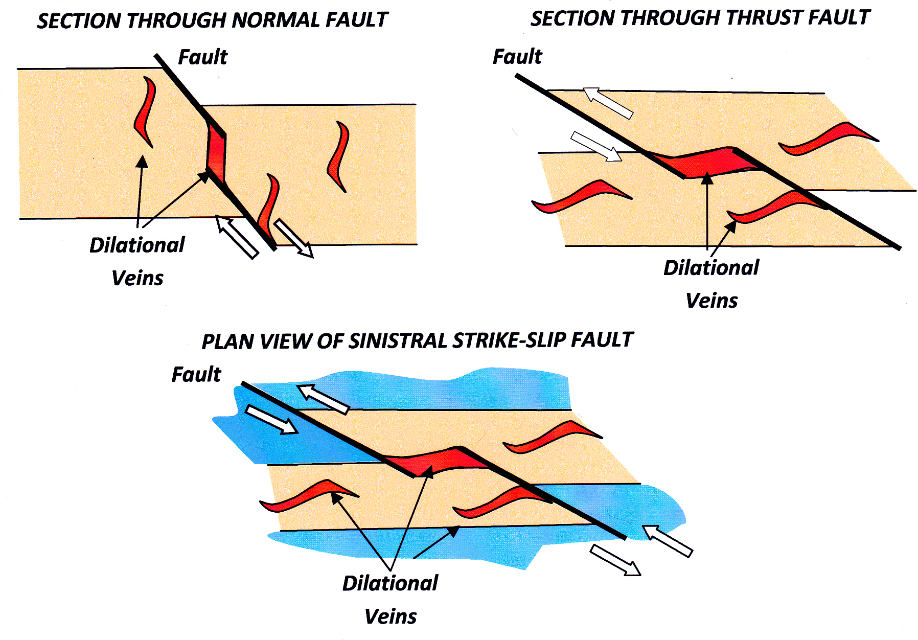
Sections illustrating the geometrical relationship of tensional openings (and hence potential sites for epigenetic ore deposits) to the three principal classes of fault. In each illustration, the principal dimension of the dilational vein is at right angles to the page.
How can we know what category of fault we are dealing with? To classify faults as normal, thrust or strike-slip, it is necessary to know (1) the attitude of the fault and (2) the movement direction (or movement vector) across it. The movement vector can be determined from the displacement of marker beds across the fault (based on field mapping or drill hole interpretations) and from observing sense-of movement indicators that can be seen in outcrop or drill core.
Once we know, or suspect, the category of fault that mineralisation is associated with, the following rules of thumb can now be used to predict the likely attitude of dilational zones and hence of high grade ore shoots within or adjacent to it. This is a simplified summary. A more detailed presentation of theory can be found in Sibson 1996 and Cox et al 2001.
NORMAL FAULTS
As already stated, Normal Faults are the commonest type of fault to form in regions of crustal extension in the upper 1-3 kms of the crust. They are the typical structures that host epithermal veins in young magmatic arcs.
The long axes of dilation zones will tend to be sub-horizontal and to lie within portions of the fault that are steeper dipping than the rest of the fault, or within steep dipping spays that trend off, or are adjacent to, the main fault (see figure above). By contrast, the shallower-dipping portions of such faults will be unmineralised or poorly mineralised. These local bends in fault attitude are known as dilational jogs (a term first defined by McKinstry in 1948). For this type of fault an initial ore discovery should be followed up by drilling a hole to along strike from the discovery hole to intersect the target at approximately the same depth. Two examples (chosen from dozens of potential examples) of epithermal vein gold mineralisation hosted within Normal Faults are shown below.
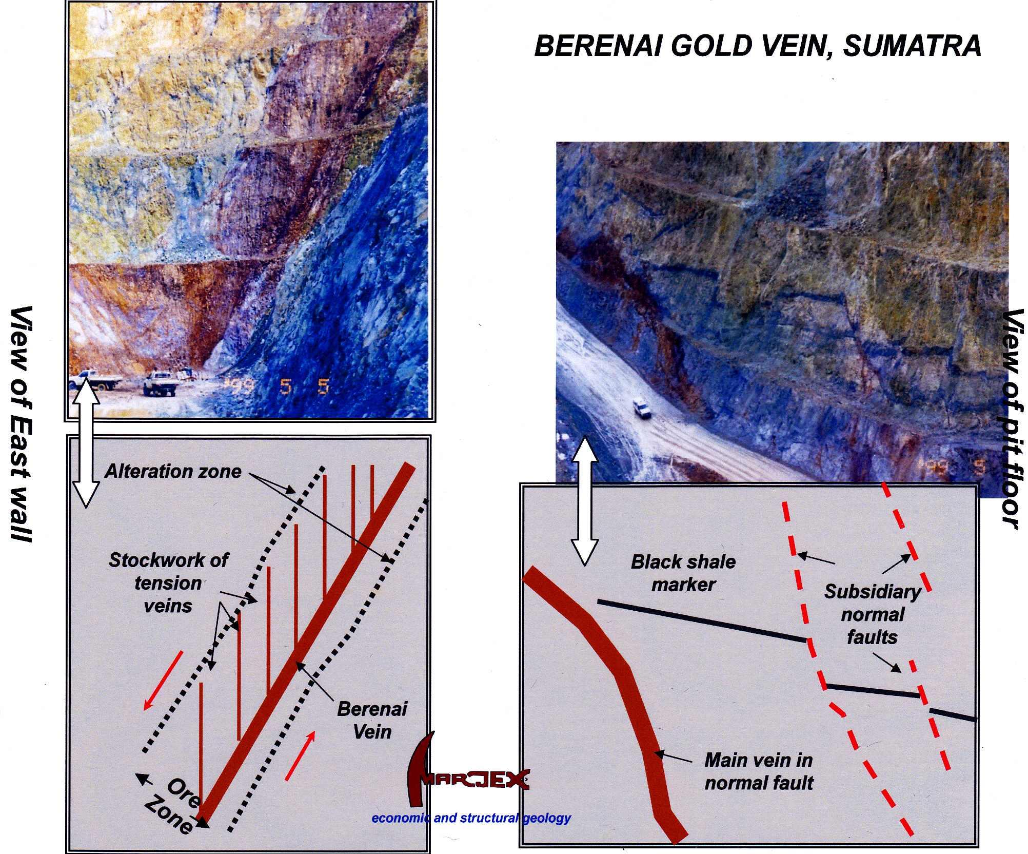
Example of vein hosted gold mineralisation: The Berenai Vein in the Rawas Gold Camp of South Sumatra, Indonesia. The red-brown colour of the mineralised zone is caused by oxidised pyrite. Figure taken from Marjoribanks 1999,
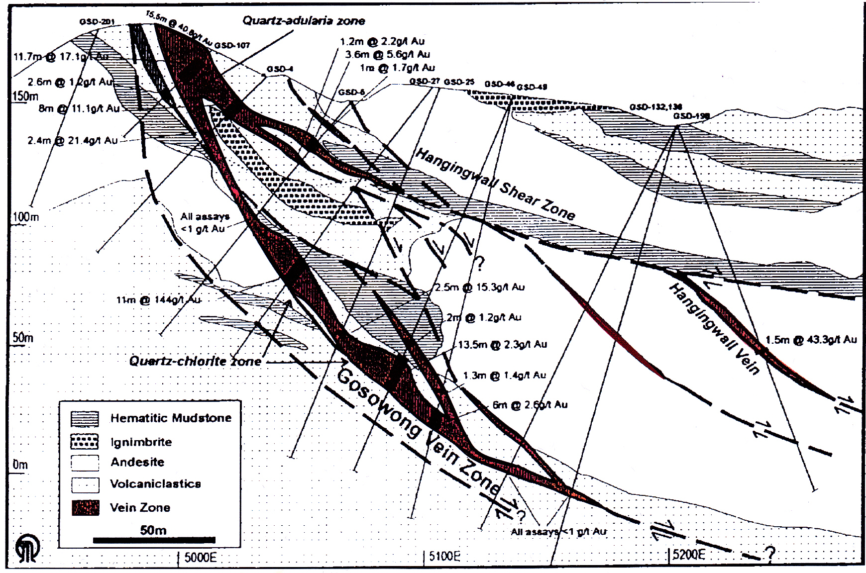
Example of an outcropping, bonanza-grade, epithermal vein hosted by a normal fault: The Newcrest Gosowong gold deposit, Halmahera Island, Indonesia. Note gold widths and gold grades show a positive linear relationship to dip on the Gosowong Fault. Figure taken from Oldberg et al, 1999.
THRUST AND REVERSE FAULTS
Shallow-dip thrusts, often located along incompetent bedding horizons, are common in the shallow levels of the crust in zones of crustal compression (orogenic zones). They seldom contain any significant mineralisation.
Reverse faults on the other hand are the characteristic type of fault to form between 3-10 km below surface and are the typical focussing mechanism for the location of mesothermal vein gold deposits in Archaean, Proterozoic and Palaeozoic slate belts.
The principal dimension of zones of relative dilation on reverse faults will tend to be sub-horizontal and lie within those portions of the fault that are shallower dipping than the main fault plane, or within shallow dipping splays that trend away from, or occur adjacent to, the main fault plane. On the other hand, the steeper-dipping portions of such faults will be unmineralised or poorly mineralised (Sibson et al 1988). For this type of fault, as with mineralisation encountered in normal faults, any initial intercept should be followed up by drilling a hole to the same depth as the discovery hole and along strike from it. I could give dozens of examples of deposits of this kind. Two are shown below:

Gold lodes hosted by tensional jogs in a fold-related reverse fault. Section through underground mine at Bendigo, Victoria, Australia (Lower Palaeozoic). The figure is taken from Cox et al, 1991.
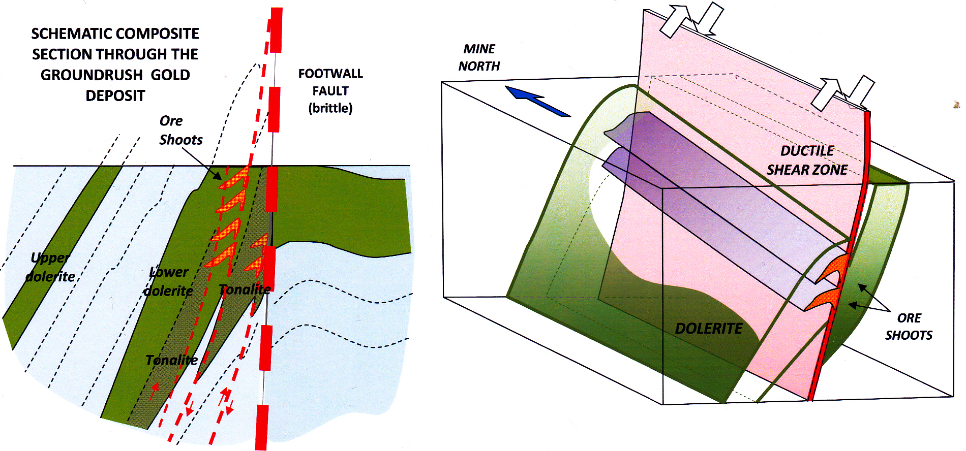
Block diagram showing the relation of gold bearing veins to reverse faulting and a favourable dolerite host rock in the Groundrush open cut gold mine, Tanami Complex (mid-Proterozoic), Central Australia. From Marjoribanks 2011.
STRIKE SLIP FAULTS
Crustal-scale strike-slip faults (think the San Andreas in California, The Tintina of the Yukon and Alaska, The Highland Boundary in Scotland, the Barisan of Sumatra, the Cadillac of the Abitibi) are known as transform faults. Transforms are tight, straight structures and poor places to look for mineralisation. However, minor strike slip faults can show the irregularities needed to focus ore veins in dilational sites.
The long axes of dilation zones will tend to be steep-plunging. For sinistral strike-slip movement, a zone of relative dilation occurs in any left-stepping bend in the surface trace of the fault. For a dextral strike-slip movement, the dilation occurs in any right-stepping bend in the strike trace of the fault. By contrast, right-stepping bends in sinistral faults and left-stepping bends in dextral faults will be zones of relative compression during fault movement and will tend to be unmineralised or poorly mineralised. Any initial ore discovery should be followed up by a deeper hole on the same cross-section. Two examples of quartz-vein hosted gold mineralisation associated with dilational sites in strike-slip fault zones are shown below:
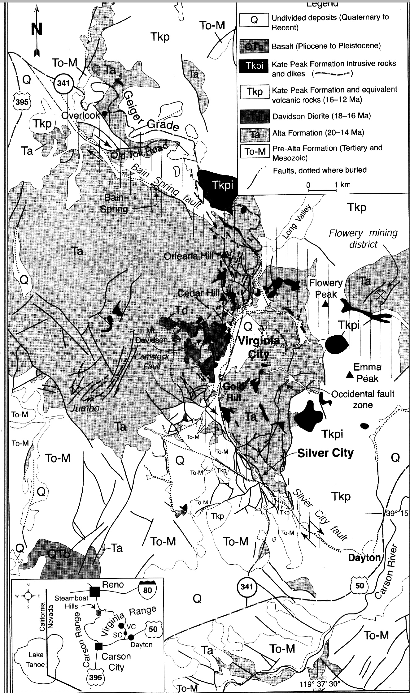
Surface geology plan of the famous Comstock Silver – Gold Camp, Nevada, USA. (click on image for full size plan). From Berger et al, 2003. For a fault analysis of this map, see cartoon below:
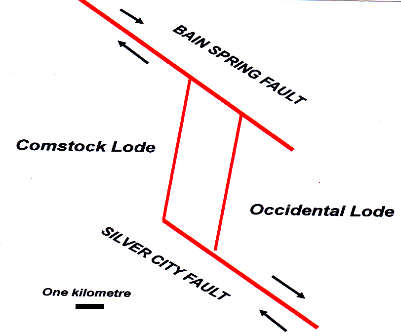
Analysis of fault patterns around the Comstock Lodes, Nevada. The mineralised Lodes are a series of normal faults that define a right-stepping dilational jog in a regional dextral strike-slip fault which carries the name Bain Spring in the north and Silver City in the south. Compare this analysis to the detailed map, above. Based on Hudson, 2003.
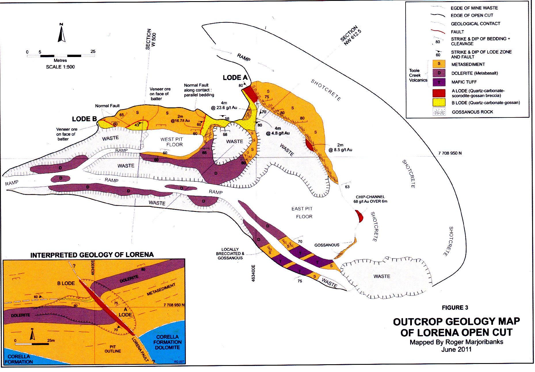
Geology map of the open cut on the Lorena high-grade, gold-arsenic Lode, Cloncurry district, Queensland, Australia. From Marjoribanks, 2011. Click on image for full size version.
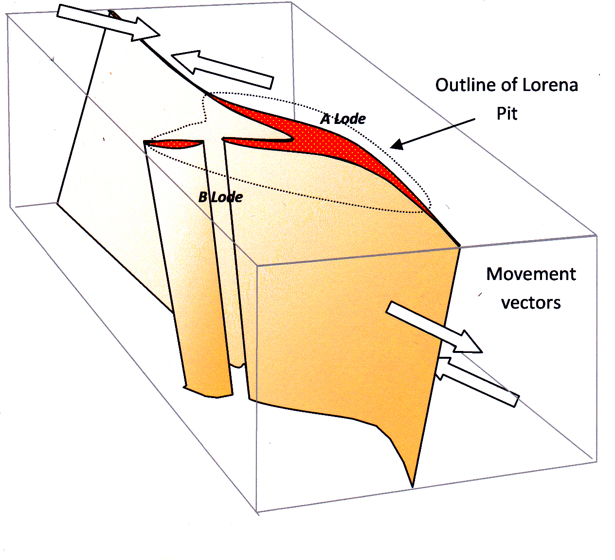 Block diagram of Lorena lode showing its interpretation as a steep-plunging dilational jog on a sinistral strike-slip fault.
DRILLING ON SECTION
Once a zone of mineralisation (potential ore) has been discovered, and its shape and attitude approximately outlined, it needs to be defined in detail by a follow-up program of in fill drill holes. Each drill hole provides a one-dimensional (linear) sample through a prospect. The problem facing the explorationist is how to use this restricted data to create a three-dimensional model of the mineralisation and its enclosing rocks. Our brains are not really very good at conceptualising complex 3-dimentional shapes and relationships (although good mining and exploration geologists can do this better at this than most). The best way to solve the problem is to concentrate drill holes in a series of vertical cross sections[5]. Each section is thus a plane of relatively high data density and will facilitate interpretation. A series of parallel interpreted drill sections are two-dimensional slices through the prospect: they can be assembled (stacked) to produce a three dimensional model. Formerly, section interpretations were often plotted onto clear perspex sheets which were then physically assembled into a frame so that they could be viewed as a whole. Today, mining software allows digitised interpreted sections to be used as a basis for creating three-dimensional virtual reality shapes of ore bodies and rock masses which can then be rotated and viewed from all angles on a monitor. Although the software allows stunning presentation of results, the key interpretation stage is still the manual interpretation of two-dimensional drill sections.
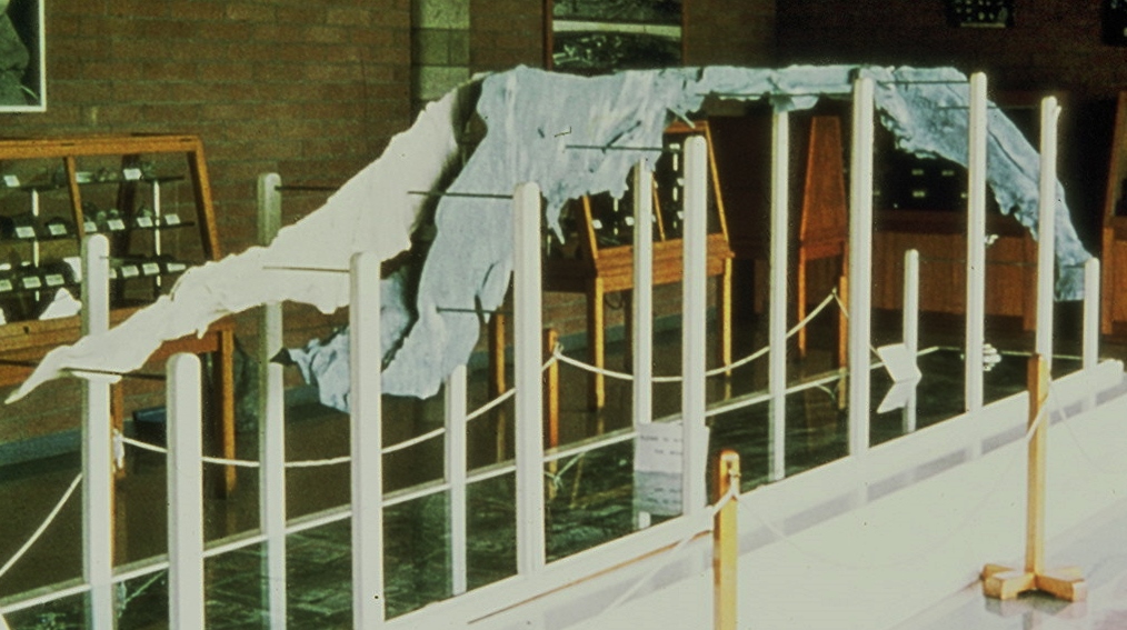
This magnificent solid model of the high grade Zn-Pb-Ag sulphide ore bodies at Broken Hill, New South Wales covers a volume that extends along strike for around 10km and to a depth of 4km. The flat top of the ore body shows where it is truncated by the surface. It was constructed from historical Level plans showing stoped out areas. Today such a model would probably be constructed using virtual reality software, but would never have the same impact.
Where drill holes deviate off section, assay and lithology data can be projected orthogonally (i.e. in a direction at right angles to the section) onto the drill section plane. Such projections are usually done by mining/exploration software programs. On these programs it is possible to specify the width of the “window” on either side of the section from which data will be projected. Obviously, if holes are not drilled at right angles to the strike of the feature, orthogonal projection will tend to distort true sectional relationships – a problem which will be exacerbated the further the data has to be projected (the wider the “window”) onto the section.
REFERENCES
Berger B.R., Tingley J.V. & Drew L.J (2003): Structural localisation and origin of compartmentalised fluid flow, Comstock Lode, Virginia City, Nevada. Economic Geology, v98, pp 387- 408.
Cox SF Knackstedt MA and Braun J (2001) Principals of structural control on permeability and fluid flow in hydrothermal systems. Econ Geol Reviews14, 1-24.
Hudson D.H. (2003): Epithermal alteration and mineralisation in the Comstock district, Nevada. Economic Geology, v98, pp 367-385.
McKinstry HE (1948) Mining Geology. Prentice-Hall, New York, 680p.
Nelson EP (2006) Drill hole design for dilational ore shoot targets in fault fill veins. Econ Geol 101, 1079-1085.
Marjoribanks RW (1999: unpublished consulting report.
Marjoribanks RW (2010): Geological Methods in mineral exploration and mining. Springer 238p
Marjoribanks RW (2011): Unpublished Consulting Report for Tanami Gold NL
Oldburg DJ, Raynor J, Langmead RP & Coote JAR, (1999): Geology of the Gosowong epithermal gold deposit. In Pacrim ’99 Conference papers pp 179-185
Ramsey J & Huber M (1983) The techniques of modern structural geology. Volume 1: Strain Analysis. Academic Press, 307p.
Sibson RH Robert H and Poulsen KH (1988) High-angle reverse faults, fluid pressure cycling and mesothermal gold-quartz deposits. Geol 16, 551-555.
Sibson RH (1996) Structural permeability of fluid driven fault fracture meshes. J Structural Geol 18, 1031-1042.
[1] Epigenetic deposits are those that formed after consolidation of their host rocks. Vein deposits are typical examples. This contrasts with syngenetic deposits, which formed at essentially the same time as their hosts. Examples of the latter are heavy mineral placer deposits or the (so called) sedimentary exhalative (SEDEX) deposits.
[2] All fault hosted ore deposits lie within zones of relative dilation. The shape of the dilation zone is a function of stress but their position, size and nature of mineralisation within them is largely a function of variations in the physical and/or chemical properties nature of wall rocks..
[3] The pitch of an ore body is the angle which it makes with the horizontal, measured within the plane of the structure which hosts it.
[4] For the purpose of this discussion, a reverse fault can be thought of as a steep dipping thrust fault.
[5]If holes are not grouped on sections but drilled with different azimuths and scattered irregularly across a prospect, combining the data points to build up a meaningful whole is much, much more difficult.