An oriented drill hole is one where the inclination and azimuth of all sectors of the hole axis are known, usually by means of a special down-hole survey. This data provides the inclination and azimuth of the longitudinal axis (the Core Axis, CA) of the cylindrical core of rock that has been extracted from the hole. However, extracted core is not fully oriented because it is always rotated by some unknown amount about the core axis and the attitude of structures within it cannot therefore be measured.
In fully oriented drill core, an additional survey procedure, called a core orientation survey, has been carried out to determine the line of intersection of the original down gravity vector across the length of the core. Drillers use special core orientation tools to do this.
Drillers use one of two methods to determine the position of down gravity vector on the surface of the drill core.
The first method is to measure the orientation of the core barrel after a run of core has been drilled, but before the core is broken free from the ground and brought to surface inside the rod string. The position of the down gravity vector across the core barrel is determined by an accelerometer built into a tool screwed onto the top of the core barrel (this is the same technology as used to orient the screen on your smart phone or tablet). The data is stored in a memory against a time stamp. After the barrel with its contained core has been pulled to surface, the barrel orientation during the time interval between core drilling and core extraction is recovered by means of an LCD readout and transferred to the last piece of core to be drilled, which, at this stage, is the piece of core gripped by the core lifter.
The idea behind this method of core orientation is that the last-drilled piece of core was attached to Mother Earth at the time the gravity direction across the core barrel was made and recorded. The orientation of the core barrel can be used as a proxy for the orientation of the core. In most cases, this assumption is valid, and the orientation of the barrel (or rather, the core lifter, an integral part of the barrel) is the same as the orientation of this piece of core. The gravity vector shown on the LCD read-out can thus be transferred by making a mark on the core. The whole drilled core run, with the drillers mark at one end, is then extracted from the barrel, placed in core trays, and delivered to the geologist. By matching broken surfaces, the geologist or geology technician then re-assembles the run on a separate channel. This enables the driller’s end-of-core mark to be transferred as a continuous Bottom Of Hole line along the length of the run.
However, the end piece of core may have broken free from the ground by the turning drill bit and rotated by some unknown amount prior to its being gripped by the core lifter. This can happen when the core contains fissile surfaces such as bedding or cleavage. Soft, incompetent surfaces such as mudstone or siltstone horizons, or gouge-filled faults, may fail through ductile shear. Surfaces at a high angle to the drill hole are more likely to fail than those at a low angle.
Where this has occurred, the driller’s orientation mark is meaningless and there is no way for the driller, and no easy way for the geologist, to know when this has happened.
Core barrel orientation tools work perfectly every time at orienting core barrels. Accuracies of less than 1 degree are claimed. But the orientation of the barrel is not necessarily the same as the orientation of the core inside the barrel.
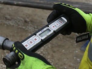
Figure 1: The Reflex ACT electronic core barrel orientation tool. The tool is screwed on to the top of the core barrel. The gravity vector across the tool is measured by an accelerometer and recovered by means of a graphical LCD display. Image from the current Reflex website.
The second method, and in my opinion a much more reliable one, is to orient the core stub before it is drilled. The core stub is the fresh broken rock surface at the bottom of a drill hole which then becomes the top surface of the next drilled run. The match between the orientation tool and the core stub is made by a percussion or wax pencil mark, a shape template, or some combination of these techniques. The gravity vector at the moment of first contact between tool and core stub is recorded by built-in mechanical system (level bubbles) or by an electronic (accelerometer) system similar to that used in core-barrel orientation tools.
In the simplest (and oldest) tool, a narrow but heavy steel rod with a pointed tip (known as a spear) is allowed to slide down the rod string on the end of the wire line after a run of core has been extracted. In angle holes the weight of the spear keeps it in contact with the lower surface of the rods. The spear then impacts the core stub making a mark (percussion or wax pencil) on the lower edge of the stub. The technique is absurdly simple, but in the hands of an experienced driller (he has to control the speed of impact) it generally gave excellent results. Although seldom used nowadays, much legacy drill core was oriented by this technique. The technique fell out of fashion not because of poor results (quite the opposite) but because its use required a separate down hole procedure after each drill run – a procedure which could take 30 minutes or more depending on the depth of the hole.
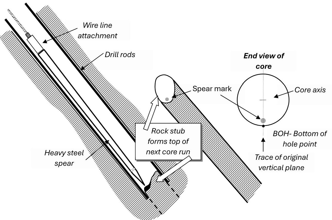
Figure 2: Operation of the simple down-hole spear core-stub orientation tool. It is lowered on the wire line after a barrel of core has been extracted to make a mark on the lower edge of the core stub. (Reproduced from Marjoribanks 2016, fig B2, p185). Down-hole Spears were usually manufactured by drilling companies in their own workshops.
More sophisticated core-stub tools operate on the same basic principle as the spear but use a template to record the shape of the stub rather than (or perhaps as well as) making a mark on the core. The template can then be matched to the shape of the stub after it has been drilled and pulled from the ground.
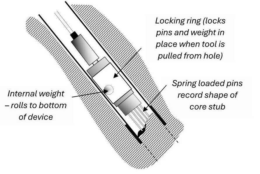
Figure 3: Operation principle of the Craelius simple template core-stub orientation tool. The procedure required a separate operation between each drilled run. This tool is no longer available, but the figure serves to illustrate the basic idea behind core-stub orientation. (Reproduced from Marjoribanks 2016, fig B3 p186).
Figure 4: The pointy end of the EzyMark core-stub orientation tool. This tool fits inside the bottom of the core barrel. The pins and wax pencil record the shape of the core stub. Lockable level bubbles inside the tool record the gravity vector at moment of contact. This all-mechanical tool is no longer available, but a close copy is available from Well Force International (see below). The red plastic block (called an OriBlock) containing the pin template and down-gravity mark is extractable from the tool and is intended to be left in the core tray as a permanent orientation record and depth marker – as seen in photo. The OriBlock system (although they don’t use that term) is also available on the Reflex VertiOri and Well Force Front end tools (see below).
The image was accessed in 2013 from the 2icAustralia company website.
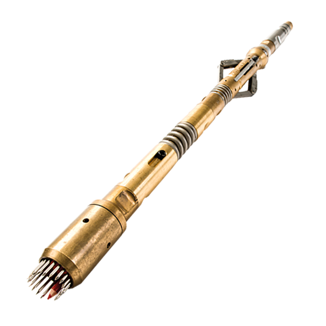
Figure 5: The Reflex Verti-Ori core-stub template tool. It fits within the bottom of the core barrel. Steel pins and wax pencil record the shape of the core stub. The gravity vector is determined by an inbuilt accelerometer and recovered by means of an electronic user interface.
Core stub tools can fail if mud or disaggregated broken core obscures the core stub, but in my experience, their failure rate is less than that of core-barrel tools. But the really important difference between the two systems is this: when core-stub systems fail, that failure is almost always obvious. In other words, results from core-stub tools are auditable at the point of core recovery and no time need be wasted marking up failed runs and making inaccurate measurements from it. And because the ways in which core-stub systems fail are different from the ways in which core-barrel systems fail, core-stub tools can produce accurate orientation in rocks where the core barrel tools fail.
Available Core Orientation tools (as of October 2023)
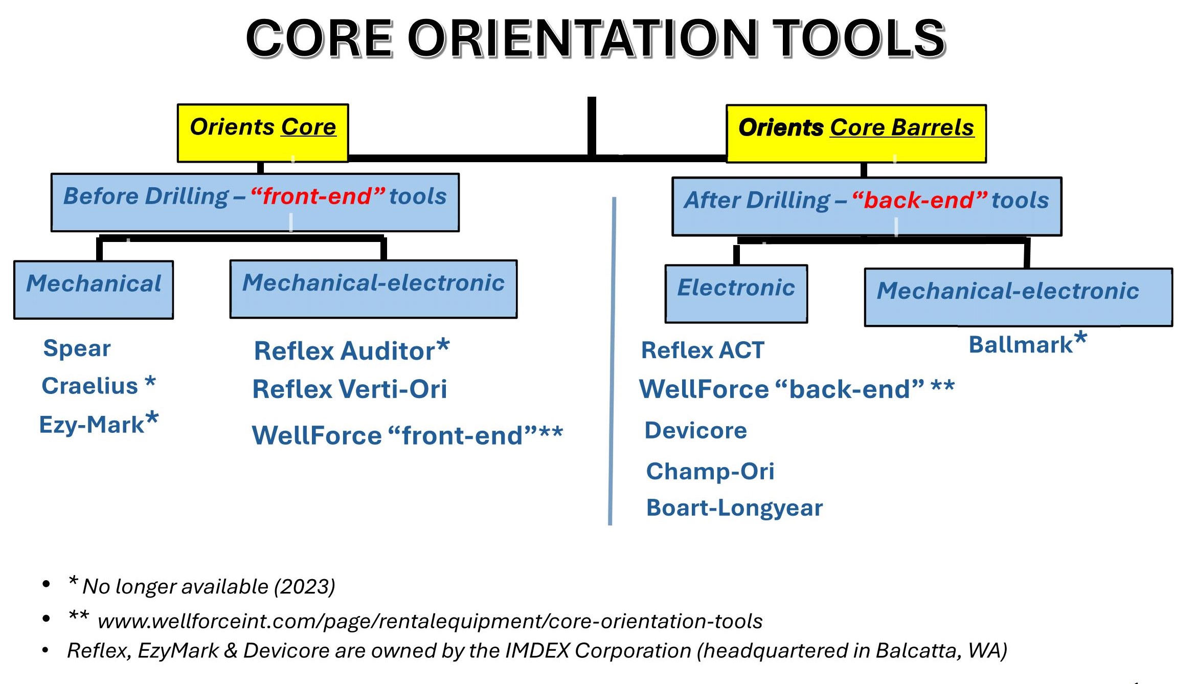
The core-barrel orientation systems that I am aware of are:
BALLMARK was an all-mechanical system, first introduced in the late 1990s but no longer available. The gravity vector was measured and recorded by the pressing of a steel ball into a soft aluminium disk at the moment of core barrel extraction. This tool (made in Orange, NSW) is the earliest core barrel orientation system that I am aware of. The company that made it may well have been the originator of the core barrel orientation as proxy for actual drill core idea.
REFLEX (their ACT™ systems LINK). Reflex is a subsidiary of IMDEX Corporation
DEVICO (their DeviCore BCT™ and DeviHead™ systems) LINK. Devico is a subsidiary of IMDEX Corporation.
BOART-LONGYEAR (their Tru-Core™ system) LINK.
AXIS MINING TECHNOLOGY (their Champ-Ori™ system) LINK. Axis is a subsidiary of the ORICA Group.
There may be other available systems that I am unaware of. As far as I can tell from website description, in their basic method of operation, all the above tools are essentially clones of each other that offer slightly different electronic user interfaces.
The core-stub orientation systems that I am aware of are the Spear (figure 2) the Craelius (figure 3), the EzyMarkTM (figure 4), the Reflex VertiOri (figure 5) and the “front-end orientation tool” made by WELL FORCE INTERNATIONAL Ltd.
The down-hole Spear system has fallen out of fashion for the reasons given above, although any drilling company could easily resurrect it.
The Craelius system is no longer available.
EzyMark was an all-mechanical system, taken over in 2014 by the IMDEX subsidiary Reflex and then marketed the EzyMark as their Reflex AuditorTM System. The Auditor tool has now (as far as I can tell) been discontinued and replaced by the Reflex Verti-Ori™ system.
The Verti-Ori system is a core-stub orientation tool with built in accelerometer and magnetometer that records the gravity vector and magnetic lines of force across the tool (LINK). By providing a magnetic vector, the tool can orient core from very steep-angled to vertical holes where gravity alone is unable to provide accurate orientation data (although EzyMark claimed accuracy for their tool in holes with inclinations of up to 88 degrees). I am informed that there are current availability problems with the Verti-Ori tool.
Well Force International’s “Front End Mechanical Orientation Tool” (LINK) is a core stub orientation tool which appears (from their website description) to be a very close copy of the now unavailable EzyMark tool of 2icaustralia.
I am indebted to Sarah Sulway (Imdex) and Olivier Cȏté-Mantha (Agnico Eagle Gold Mines) for some of the details in this post. All expressed opinions are of course mine.
You can read my previous (2013) post on this subject HERE
Reference:
Marjoribanks R W 2010. Geological Methods in Mineral Exploration and Mining. Springer pp238. ISBN 978-3-540-74370-5.