Planar Structure
Strike and dip are conventions for measuring the attitude of planar structures in rocks (bedding planes, faults, joints or veins), in terms of the angles which they make with the geographic coordinates of the earth’s surface: north-south, east-west and up-down.
You know all this of course: they are among the first things you learn in geology. But bear with me, I intend to start with basic definitions and work my way up to ideas which may not be so familiar.
The Strike of a planar structure is defined as the orientation of a horizontal line on its surface using the 360° clockwise-arranged divisions of the standard compass.
If the line of strike trends north its strike is ooo degrees; if north-east its strike is 045°; south is a strike of 180°; NW a strike of 215° and so on. Strike is an open-ended line, not a vector. Every line has two ends, so strike can be expressed by either of two compass directions – 045° strike could be quoted by its reciprocal 225°; 215° strike as 135° etc.. There is no general rule as to which you should record, unless you are using the Right-Hand-Rule – of which more later.
Note that a geology plan shows a horizontal slice through a volume of rock and thus shows the distribution of strike. Conversely, a geology section shows the distribution of dip. But a geology map is only a plan where the surface being mapped is approximately flat and horizontal and/or the structures being recorded have vertical or near vertical dips.
The Dip of a surface is the acute angle which it makes with the horizontal. The measurement is the angle it makes below the horizontal in a notional vertical plane at right angles to the strike. Dips range from 00° (horizontal) to 90° (vertical). A measurement made this way is known as the True Dip. If the measurement is made in any plane other than that at right angles to the strike, it is an Apparent Dip. Apparent dips are always less than true dips. You may not be sure whether your dip reading is apparent or true, but you can be sure that the true dip is at least as great as the figure you have obtained.
When recording strikes and dips, it is a convention that a three-digit number is used for the strike and a double-digit number for the dip. In this way, the two measurements can always be distinguished.
Some geologists quote a strike as being so many degrees east of north. Don’t do this. Compass directions should always be quoted in degrees clockwise from north. Any other way is sloppy and unscientific.
To define the attitude of a planar surface encountered in outcrop or drill core a geologist needs to know its strike, its dip and the direction of the dip towards one of the principal quadrants of the compass. When compiling a geological map, strike is the most important measurement, because it is strike which defines potential continuity of the surface in the horizontal plane of the map. Conversely, when compiling a section, dip is the most important number.
When measurements are recorded digitally (as opposed to analog recording as an oriented symbol on a map) the most common traditional way has been in the form of xxx/yy /A, where xxx (the strike) is a 3-digit compass bearing, yy (the dip) a two digit number representing the angle from the horizontal and A the direction of dip towards a principal compass direction: N, NE, E, SE, S, SW, W or NW.
As an example: 042/23 NW is a surface with strike of 042° that dips at 23° to the northwest. Because this method requires three data fields, the advent of computer databases has led to the use of dip and dip direction, because recording information in this manner needs only two data fields. In this recording system the dip measurement is as described: the dip direction is a compass bearing at right angles to the strike, measured in the direction of the dip. The code is written in the form of yy/zzz or yy to zzz.
It is simple mental arithmetic to derive a strike/dip/and dip direction from a dip/and dip direction, or vice versa.
The Right Hand Rule
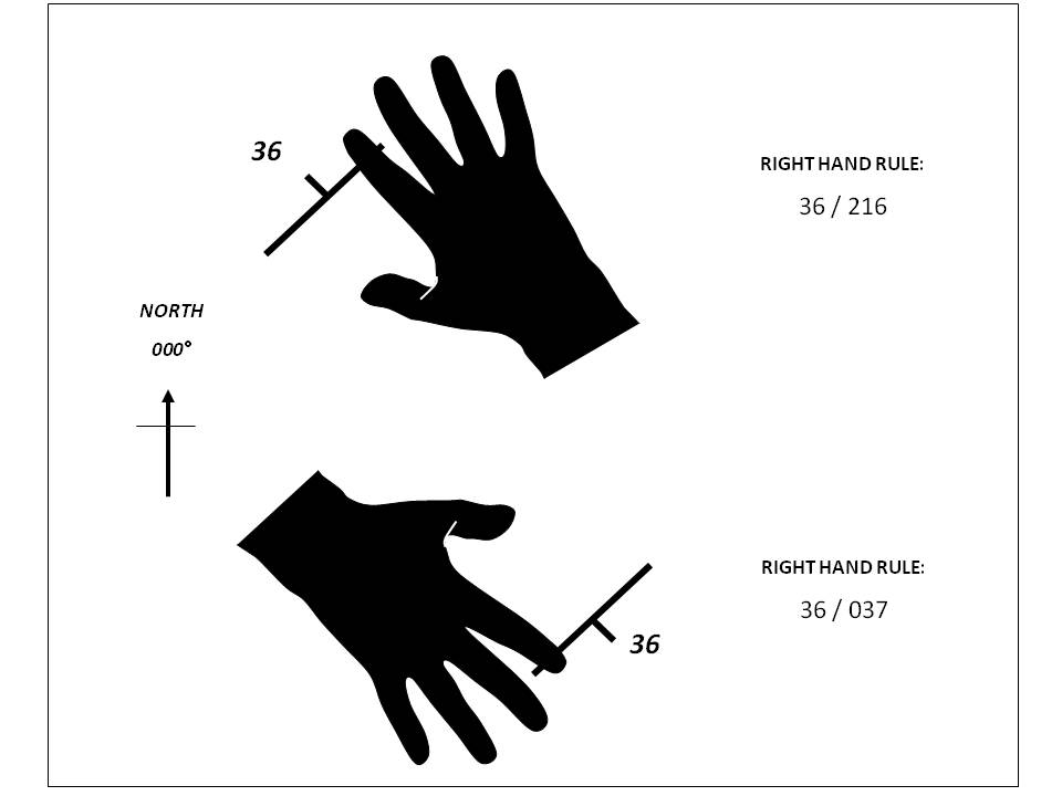 The Right Hand Rule for recording dip and strike measurements
The Rule is a simple way of recording the strike of a plane and the direction of its dip. In this method, the plane is measured and recorded as its strike and dip but the all-important dip direction qualifier is indicated by means of a convention in the way the strike is expressed. The convention can be described thus: imagine grasping a strike/dip map symbol with your right hand, palm down and fingers pointing in the direction of dip. Your thumb then indicates the strike direction to be recorded. For example: an east-west strike (090°-270°) with a 60° dip to the north would be recorded as 270/60. A record of 090/60 would indicate the same strike but a dip of 60° to the south.
The right-hand rule is an excellent system but has one disadvantage – a near fatal one in my opinion. Since the Rule is not universally employed, you can never be sure when looking at someone else’s map, table or report that it has been used, unless the geologist specifically and prominently draws your attention to its use. In the absence of such information, it might be wrong to assume that an attitude quoted as yy/xxx involves the Right Hand Rule. Some other convention might be involved or (more likely) the geologist simply forgot to add the dip qualifier.
Comparison of the three measuring conventions for the attitude of planes
Strike/dip/dip direction Right Hand Rule Dip/dip direction
xxx/yy/A xxx/yy xx to zzz
037/36 SE 037/36 36 to 127
217/36 SE 037/36 36 to 137
037/36 NW 217/36 36 to 307
Linear Structure
Linear structures in rocks could be the long axes of cylindrical folds, the intersections lines of planes of differing orientation, the preferred orientation of elongate minerals or mineral aggregates or the elongation (stretching) of phenocrysts and clasts as a result of ductile deformation.
The attitude of linear structure is measured and recorded as its trend and plunge.
Trend is a vector that points in the same the same direction as the plunge. It is measured by holding a compass vertically above the linear and recording the direction as a compass bearing or by an arrow on a map.
Plunge is the acute downward angle that a lineation makes with the horizontal of a notional vertical plane passing through it. A measurement recorded as 76/067 represents a plunge of 76° to 067°.
If a lineation is exposed on a structural plane of the rock, rather than directly measuring trend and plunge, it is generally easier to measure its pitch on that plane (pitch is an old Cornish miner’s term). Measurement is made on the surface of the plane and Pitch is the angle which the lineation makes with the strike of the plane. Knowing the attitude of the plane, the pitch enables the trend and plunge of the linear to be easily calculated. The simplest way to do that is by means of a stereonet.
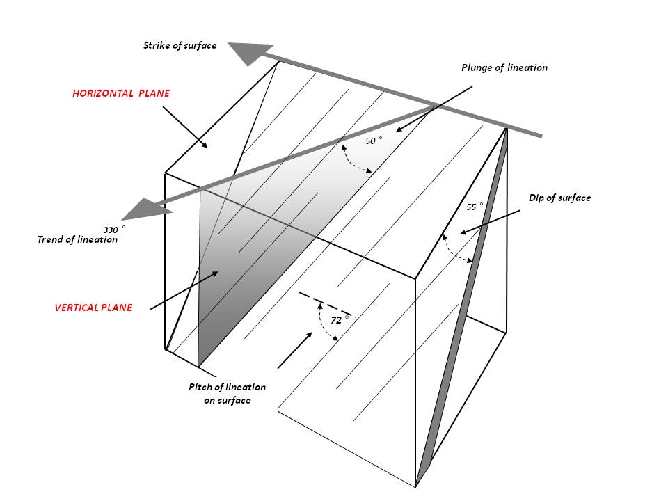
Block diagram illustrating the strike and dip of a plane, the trend and plunge of a lineation on a plane and the pitch of a lineation on a plane.
Any computer software that you employ should be capable of accepting and presenting data in all the above formats.