All metal deposits that have formed later than the rocks that host them (that is, epigenetic deposits) have got there by virtue of fluid transport along faults. The location, shape, size and attitude of faults are largely determined by the strain states that existed within the fault and its immediately adjacent rocks during their formation. The most important structures for any explorationist to understand are faults.
What is a fault? The answer seems so obvious that few geologists (or textbooks) ever bother with a definition. When geologists think of a fault, they have in mind a fracture where the rocks on either side have slid past each other with the direction of movement lying in the plane of the fault itself. Most geological dictionary or structural geology textbooks reflect this same misunderstanding with a definition that specifies a direction of movement along the plane of the fault. For example, the Glossary of Geology[1] with 36,000 defined terms defines a fault as:
A fracture or zone of fractures along which there has been displacement of the sides relative to one another parallel to the fracture.
The Oxford dictionary of geology and earth sciences[2] offers this:
Approximately plane surface of fracture caused by brittle failure and along which observable relative displacement has occurred between adjacent rocks.
Hobbs, Means & Williams in their well-known textbook[3] provide this definition:
A (fault is a) planar discontinuity between blocks of rock that have been displaced past one another in a direction parallel to the discontinuity
However, these definitions are inadequate because they specifically define fault movement as taking place parallel to (or along) the fault plane. If that criterion is strictly applied, it would exclude almost all structures that geologists normally understand by the term fault, as I hope to demonstrate shortly.
The definition of a geological fault in Wikipedia[4] , by leaving out the requirement for movement to be parallel to the fault plane, provides much the best definition of a fault that I have yet found:
A fault is a planar fracture or discontinuity in a volume of rock across which there has been significant displacement…
However, Wiki spoil their definition by using the qualifier “significant”. The Oxford lexicographer provides much the same restriction with his requirement for fault displacement to be “observable”. Which begs the following questions:
How much displacement does there have to be for it to be significant?
Is there a cut-off point in the amount of displacement at which the structure ceases to be a fault and becomes something else, unspecified?
If the structure is not observed to intersect a fortuitous marker bed, is it then not a fault?
If the fault does intersect a marker bed but that marker shows no apparent displacement on the observed face or section, is it not a fault?
So, to avoid these problems, here is my definition:
A fault is a restricted tabular zone of relatively high strain, with displacement of the rocks on either side relative to each other.
To justify my definition and explain why previous definitions that are out there are inadequate, it is necessary to go into some detail on how rocks deform. And in order to do that I must first define the terms that I will use.
Definitions
The direction of relative movement of the volume (block, mass) of rocks on one side of the fault with respect to the volume on other side is called the Fault Movement Vector (FMV). On a two-dimensional section across the fault in the plane of the vectors the FMVs can be represented by a pair of parallel but opposed arrows as shown on Figure 1. Note that the vectors are based on the final displaced position of the two blocks at the end of any given fault movement and do not necessarily show the route by which each block traveled to arrive at this final position.
If a marker bed is intersected by a fault it may or not show a lateral displacement across the fault. Even if there is a displacement, that displacement may or not be parallel to the FMVs. Any lateral displacement of a pre-faulting marker unit across the fault can be shown on a plan or section by a pair of opposed arrows on that section. I will call these arrows Marker bed Displacement Vectors or MDVs. MDVs are always parallel to the fault plane.
The difference between FDVs and MDVs is that FDVs describe the relative movement between the volumes of rock on either side of the fault, whereas MDVs only describe the displacement of a particular pre-fault marker structure across the fault. Marker beds with different orientation may give diametrically opposed MDVs across the same fault. FDVs are the more fundamental measure of fault movement.
The Nature of Faults
The amount of movement that has taken place across a fault can vary through several orders of magnitude – from a fraction of a millimetre to hundreds of kilometres.
- Small, locally developed, fracture surfaces across which insignificant displacement has taken place are called joints. By “insignificant” I mean difficult or impossible to see with the naked eye. Joints are presumably the category of fracture which the Wiki and Oxford lexicographers sought to exclude from their definition by their requirement that fault displacement be “significant” or “observable”.
- Joints form in exactly the same way as faults and should be regarded as a sub-category of faulting.
- Faults are not mathematical planes (two-dimensional surfaces with length and depth, but no width) but a three-dimensional tabular zone of deformed rock. The length and depth of a fault is always much greater than its thickness, but fault width or thickness can range through many orders of magnitude.
- No fault is ever strictly planar. Normal and Thrust faults (more on these later) are typically curved: steep dipping near the surface and progressively flattening with depth – a shape known as listric. In addition, at all scales, faults show irregularities – bends and bumps and jogs. During fault movement the variations from strict planarity lead to complex patterns of stress along the fault surfaces. These stress variations are the key to understanding the location and shape of ore that might form within the fault zones.
- The Fault Movement Vectors can lie at any angle to the fault surface. Where the FMVs are parallel to the fault plane the fault has formed by a deformation mechanism known as Simple Shear. Where the FMVs are at 90° to the fault surface, the fault structure has formed through the process of Pure Shear. Where FMVs lie between 0˚ and 90˚ to the fault plane deformation is accomplished by a mixture of both simple shear and pure shear mechanisms.
- In Simple Shear faults, the rocks on either side of the fault zone have moved laterally with respect to each other.
- In Pure Shear faults, the rocks on either side of the zone have either moved towards each other in compression or moved apart in extension[5]. For this to happen, there must be a reduction or increase in the volume of the rocks affected by the external stress field.
- Most fault zones are the result of both simple shear and pure shear deformation, and the relative proportion of these two processes can vary both across and along the fault zone.
- Because changing the volume of rocks is difficult, they deform much more easily by the mechanism of simple shear than by pure shear. Thus, displacements of more than a few meters indicates that the dominant mechanism was probably that of simple shear. Note the deliberate use here of the vague terms: “dominantly”, “more than”, “few” and “probably”. In dealing with real rocks in the field, as opposed to simplified textbook examples, that is the best that can be done.
- Because of (10) above, the most commonly occurring map-scale faults are those where the amount of displacement attributable to simple shear is greatest.
As rock is incompressible, faulting can only reduce its volume by the physical removal of material from the faces of the fault zone. This happens predominantly by means of selective solution (or in extreme cases, melting) of rock material into fluids within the fault zone. The process is promoted by high temperature and high confining pressure and controlled by the chemical/mineralogical nature of the affected rocks. The dissolved material in solution moves along (laterally and upwards) the fault zone. Movement is driven by pressure and temperature gradients as well as by the “pumping” effects of periodic seismicity[6]. It will ultimately be deposited as vein material (typically quartz or calcite) elsewhere in the fault in regions that are under relative tension. Left behind in the fault zone are the relatively insoluble rock components such as clay or graphite. Any puggy, clay-rich material in a fault is the insoluble residuum of material lost through pressure solution during pure shear compression. This type of fault fill is usually described as fault gouge.
Rocks have little strength under tension, especially in the upper few kilometres of the crust where confining pressure and temperature are relatively low. Pure shear extension creates fractures – planar zones of extension – that (unless at or near the surface) will suck in fluids from along the fault zone or from adjacent rocks. The presence of such pressurized fluids can aid the propagation of a tensional fracture. The fluids deposit vein material in the fracture. Igneous fluids (magma) may crystallize as dykes or sills. Vein filled zones in former tensional sites of a fault are the so-called “dilational jogs” that host many epithermal ore deposits.
The important point to remember is that pure shear deformation, as opposed to simple shear deformation, always results in a change in volume – either an increase or a decrease – of the affected rocks.
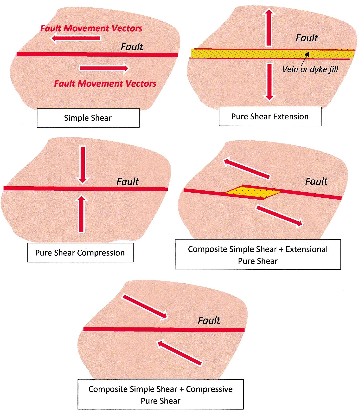
Figure 1: The diagram shows a series of two-dimensional sections through rock bodies affected by different dynamic styles of faulting. The opposed paired arrows are the Fault Movement Vectors and indicate the relative net movement of the rock volumes on either side of the fault trace. The sections are in the plane of the FMVs. Where the vectors are parallel to the fault plane, the opposed blocks have moved laterally past each other. However, FMVs can lie at any angle to the fault plane and this causes some degree of compression or extension stress across the fault. Two end member states, either of pure compression or pure extension, occur where the vectors are normal to the fault. There is a continuum between the different styles of movement, not just between different faults, but within any one fault at different places and at different times during its formation. Click for larger image.
Simple shear and pure shear faults are end members of a continuum of styles of rock fracture. Even where simple shear might be the predominant mechanism of fault displacement, different parts of the fault will locally exhibit the effects of pure shear. Conversely, in dominantly pure shear structures, there will be zones where the structures observed formed through the mechanism of simple shear.
Faults develop incrementally over geological time through the accumulation of large numbers of relatively small movements. During this process, each part of a final fault structure may have been sequentially subjected to, and show the effects of, both displacement mechanisms. Therefore, in addition to evidence for different structural process that operated in different parts of a fault at one time, at any one point in a fault different styles of faulting may have operated over time. Typically, early formed structures are destroyed by later movement, but this is not always the case.
The descriptive nomenclature of Simple Shear Faults
It is not always possible to determine fault mechanism. In this case, a descriptive nomenclature with no genetic implications can be applied based on the observed displacement of a marker bed across the fault as observed in outcrop, section or plan. This sense of displacement is either in a direction parallel to the strike of the fault (known as strike-slip); or parallel to the dip (dip-slip), or some intermediate direction between the two (oblique-slip).
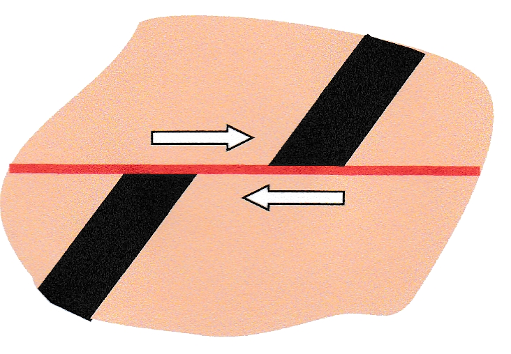
Figure 2: A randomly oriented section through a fault intersecting a marker bed. The arrows indicate the displacement of the bed. They are Marker bed Movement Vectors or MDVs. MDVs are not the same as Fault Movement Vectors. They are only parallel to FMVs in Simple Shear faults where the section lies in the plane of the FMV. Displacement arrows such as this on a plan or section, and the terms strike-slip, dip-slip or oblique-slip which describe the sense of displacement relative to external geographical coordinates, are descriptive only, and have no genetic implication. Click for a larger image.
Where faults are determined as resulting from dominantly simple shear mechanisms, they can be classified according to their orientation and sense of displacement into Transcurrent, Normal or Thrust faults. Transcurrent faults are strike-slip. Normal and Thrust faults are dip-slip. Reverse faults are usually included in this scheme as steep-dipping Thrust faults. This 3-fold classification of faults (four, if you count Reverse faults separately) is is often called “Andersonian” after the Scottish geologist Ernest Anderson who first proposed it in 1905[7] The classification reflects the orientation the three orthogonally resolved principal external stress axes (greatest, least and intermediate) in the upper part of the earth’s crust. Here, these axes are dominantly either parallel to the surface or at right angles to it[8]. If the principal stress direction is vertical, Normal faults may form; if the intermediate stress direction is vertical, Transcurrent faults form; if the least stress direction is vertical, Thrust or Reverse faults form.This is certainly a simplification, but Anderson’s classification of simple shear faults stands up remarkably well.
Consider an orthogonal section across a simple shear fault with a dip-slip displacement that affects a flat-lying sequence (Figure 3). The fault (if dipping less than 90˚) will separate a hanging wall block from a footwall block. Where the hanging wall has moved up relative to the footwall, such faults are called Reverse or, if the dip is less than around 45˚, they are called Thrust faults. In all such faults, the movement has shortened the affected rock sequence in the horizontal direction but increased it in the vertical direction. There is no volume loss. If Reverse or Thrust faults affect shallow-dip strata they can cause repetitions of marker beds on vertical sections.
Where the hanging wall block has moved down relative to the footwall, dip-slip faults are called Normal. With Normal faults, the affected rocks have been extended horizontally and compressed vertically. Where Normal faults affect shallow-dip strata, elements of the sequence might be missing on vertical sections.
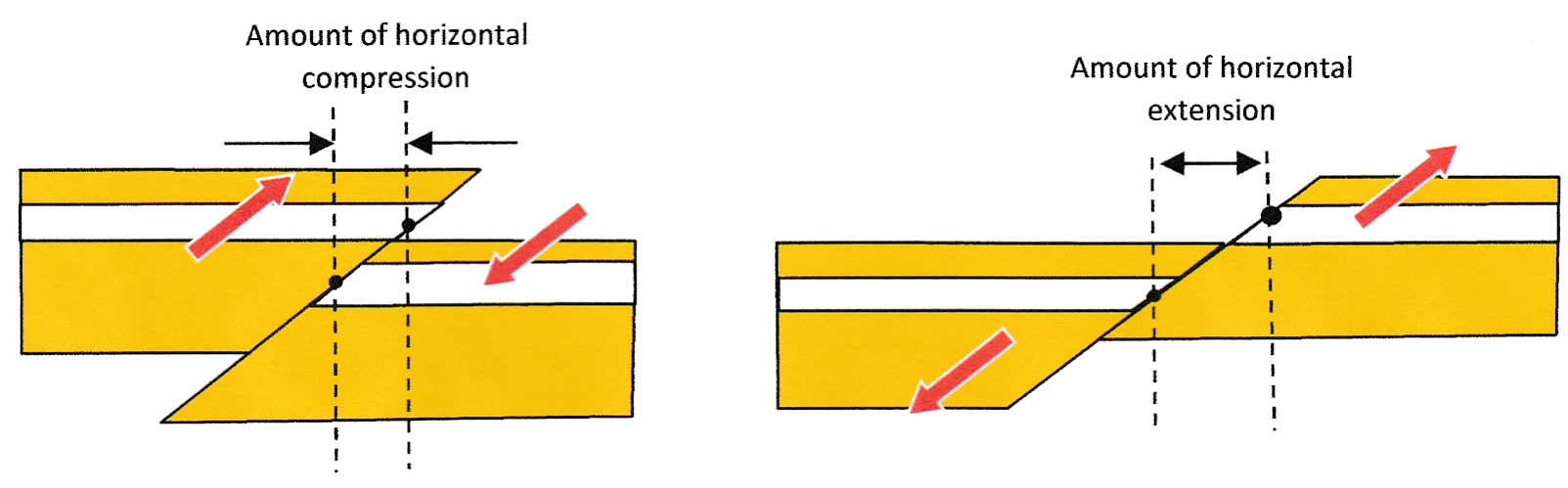
Figure 3: Vertical sections through dip-slip Simple Shear Faults drawn in the plane of the Fault Movement Vectors (red arrows). On the left, Thrust Faults leading to horizontal compression and vertical thickening of a sequence. On the right, Normal Faults leading to horizontal extension and vertical thinning. Click for a larger image.
Recognizing Dominantly Pure Shear Faults
During their formation, extensional faults move rocks apart and create a new volume which (except at the surface) in its formation will sucks in fluids from further along the fault zone or from the adjacent rock volume. These fluids are from hydrothermal or igneous sources. The fluids deposit vein material (typically quartz or calcite) or will crystallize as an igneous dyke. The presence of this epigenetic material in the fault plane is the main way of identifying such faults.
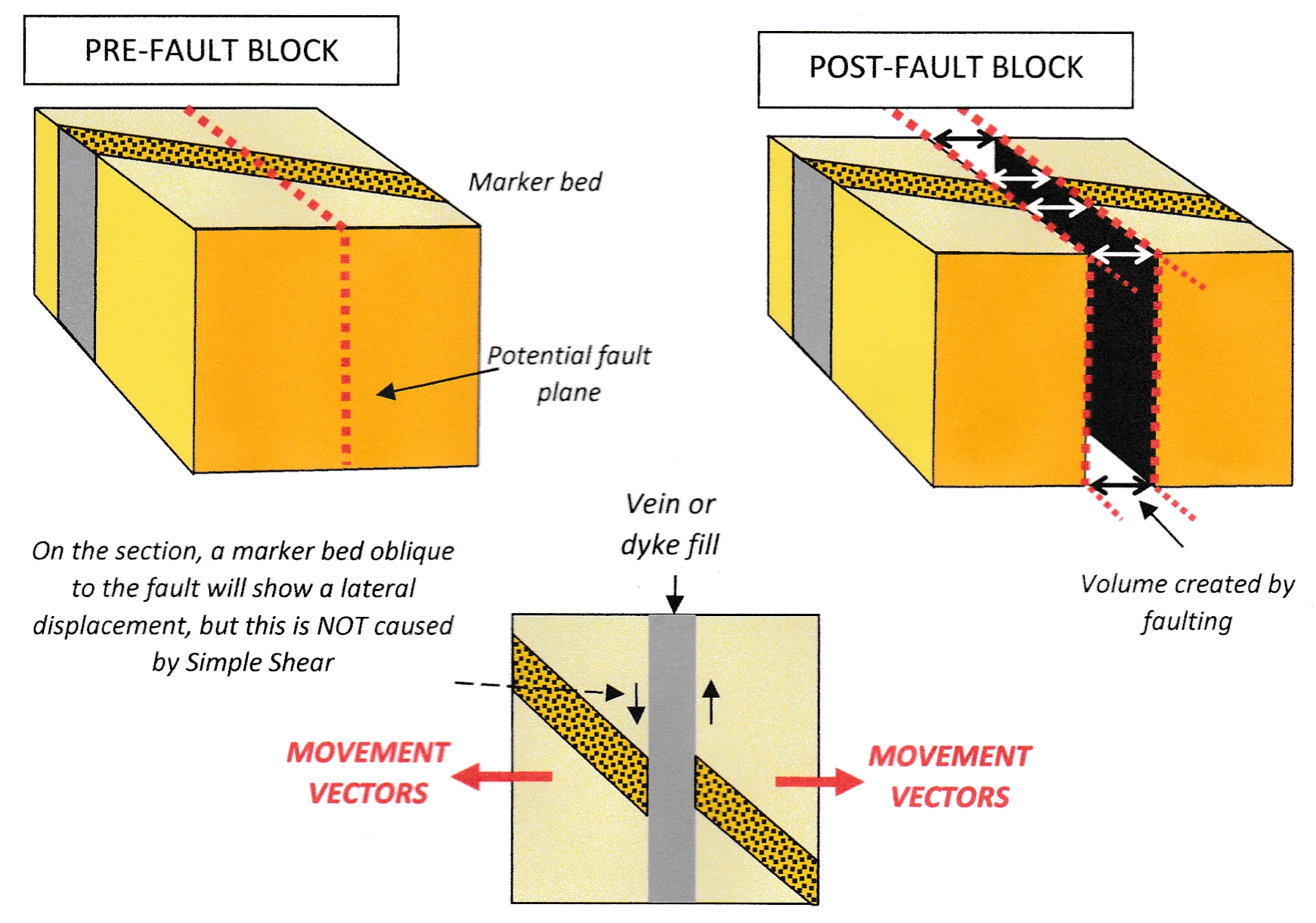
Figure 4: Before and after block diagrams along with a plan view of an Extensional Pure Shear Fault and its effect on a marker bed. Note, on the plan view, the displacement of the marker bed is not the result of simple shear faulting. Click for a larger image.
A pure shear compressional fault has lost material from the fault face. The presence of clay gouge in the fault zone indicates that material has been lost through pressure solution. Other structures that may be present in the fault zone such as fine penetrative cleavage parallel to the zone margins, are also indicative of compression.
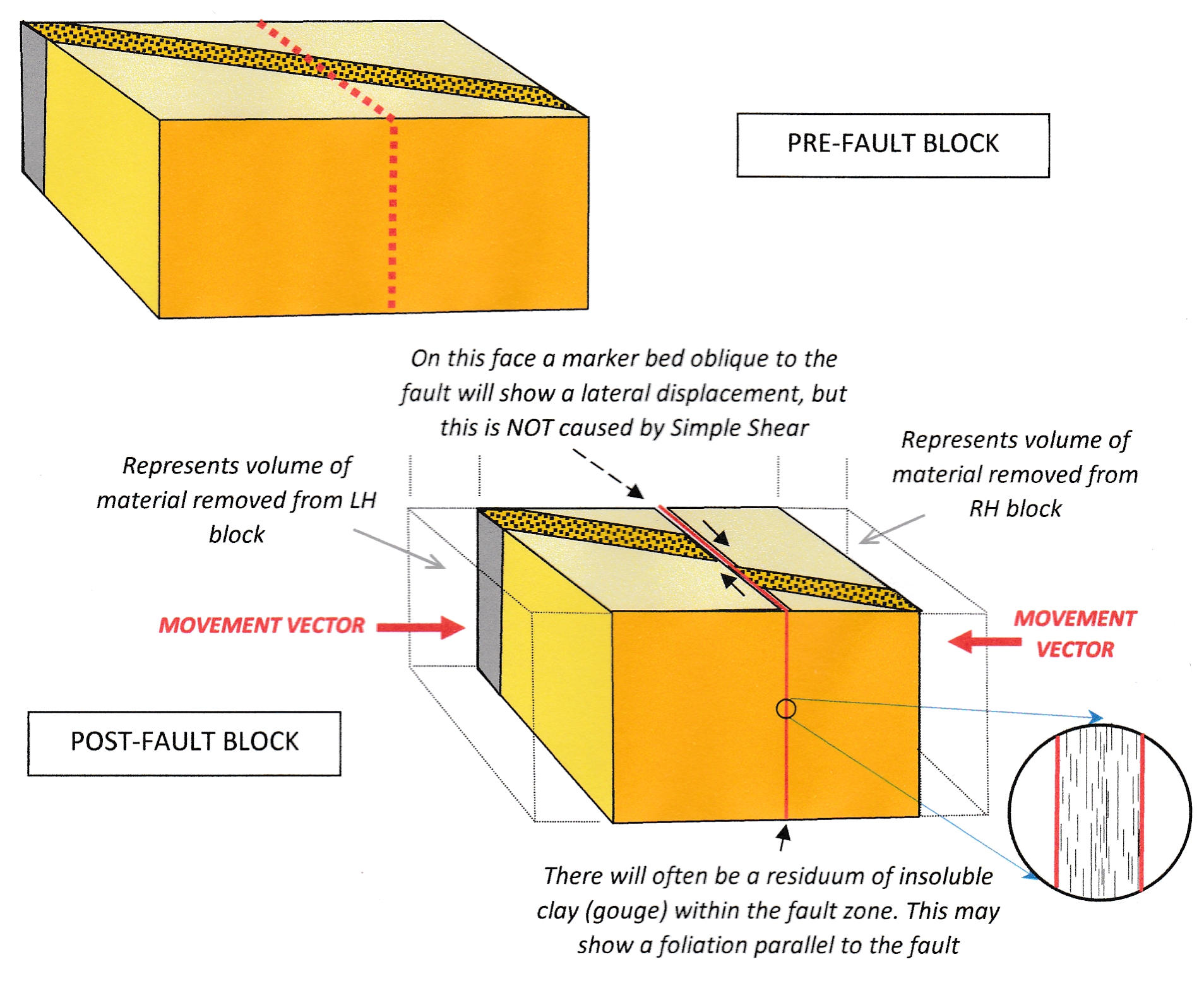
Figure 5: Before and after block diagrams of a Pure Shear Compressional Fault. Note that the dextral strike-slip displacement of the marker bed across the fault is not caused by simple shear. Click for a larger image.
The displacement of marker beds
Any marker bed intersected a fault will be displaced by an amount which depends on the angle which it makes with the FMVs, measured in the FMV plane. If the angle is 0˚ there will be no apparent displacement of the bed on that section. The displacement of the bed will increase with increasing angle. Maximum displacement is reached when the angle is 90˚ (see Figures 3, 4 & 5). This is a simple geometrical consequence and applies whether the fault mechanism is simple shear or pure shear.
First posted November 2013 Modified July 2020
[1] J A Jackson & R L Bates (eds), 1980: Glossary of Geology. Published by the American Geophysical Institute, 2nd Edition, 1980.
[2] Michael Allaby 4th Ed. 2013 online version. DOI: 10.1093/acref/9780198839033.001.001
[3] Hobbs B E, Means W D & Williams P F, 1976: An outline of structural geology. John F Wiley and Sons, 571p.
[4] Accessed July 2020
[5] I have always found the terms “simple shear” and “pure shear” unfortunate and non-intuitive. For a start, the word “shear” or “shearing” in all non-technical dictionaries refers only to the lateral movement of two bodies past each other. And what is the logic in calling one type of deformation “simple” and one type “pure”? However, the terms are long established and well defined in rock mechanics. We have to live with them.
[6] Sibson R H, Moore J McM & Rankin A H 1975: Seismic pumping and hydrothermal fluid flow transport mechanisms. Jour. Geol. Soc. London v131, pp 653-659.